This thread has been locked.

If you have a related question, please click the "Ask a related question" button in the top right corner. The newly created question will be automatically linked to this question.

TPS40210 overcurrent problem starting with PWM PID

Other Parts Discussed in Thread: TPS40210, TPS40210EVM

Hello.

My appliance is a DC/DC converter 7-36V IN and variable 24-52V OUT 1A max current. Only under certain conditions they experience starting trouble.
Example:
Vin 12V
Vout 24V
Power 3,5W
In this condition the swicthing starting, but after 1 second stops for overcurrent protecntion. Every 4 seconds tryes to start.
If exclude the PWM Vout control, and fixing reference with resistive net, the switching always starts.

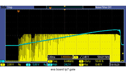
PWM is 48,24kHz 3V with 69,13% of duty-cycle.

Thanks

E.

  • Hello, 

    Can you probe ISNS signal to check if OC is triggered? Please provide the waveform. 

    Also, do you have a chance to measure bode plot to check if loop is stable?

    Thanks

    Qian

  • Hello,

    I have both oscilloscope and VA, but do not know how to measure the loop.
    This is capture for 12Vin and 24Vout.
    I reached the boot with a softstart software with PWM (duty cycle ramp from 100% to 68% ad 48kHz in 8 seconds), but sometimes it resets the CPU, and obviously the PWM ramp 

    This is capture for 22Vin and 24Vout.

    This is the capture in the moment of overcurrent. The spike happening every 4 seconds and the Vout is same the Vin, 12V....

  • Hello,

    Are you using eletronics load in the test?
    Some eletronics load has inrush current when it starts to draw the current.
    Can you use a current probe to check if there is inrush current on eletronics load?

    Thanks
    Qian
  • Hello,

    no, i using a real load, an wireless AP powered over ethernet at 24V.

    This is Vin, from a laboratory power supply, with 7A current limit.

    Acquisition, in voltage and in current.

    Blu trace is current, 100mV/AMP

  • Why the VIN rise up suddenly and then falls down slowlly?

    Attached is the review on schematic. Please follow the suggestions.

    Please remove R38 and C33 to check if they are related to the issue.

    The compensation values needs to be updated.

    TPS40210 review.pdf

  • Hello,

    I try to change the values of compensation net as your scheme. And I removed R38 and C33. I applied all the recommended changes (C20 is 4,7uF).
    The output is fixed at 24,7V.
    With Vin >9,5V the switching start, with Vin <9,5V don't start.

    There as the traces:

    The blue line is output with load (real) connected.

    Regards
    E.

  • Hello,

    I'm a little bit confused. You said Vout is fixed at 24.7V, but blue line in waveform shows the Vout is up and down.

    Which one is correct? Is there any issue now?

    Thanks

    Qian

  • Hello,
    Of course, the compensation network is calibrated on 24,7V. But switching not start, only attempts.

    Regards
    E.
  • Do you still see the OC on ISNS pin?
    Can you use a current probe to measure the inductor current to see if there is real OC?

    Can you probe Vin, VOUT, GDRV, ISNS, FET drain, and zoom in the waveform when converter stops switching?
    Please set probe bandwidth at 20MHz.

    Also, in your previous waveform, it shows VIN rise up quickly and drops, do you know why?

    Thanks
    Qian
  • Hello,

    I will make the measures quickly...

    ..."Also, in your previous waveform, it shows VIN rise up quickly and drops, do you know why?"...

    Is a normal situation, the TPS40210 don't start and tries to reboot every 4 seconds, according the value of C17 (1uF) in the SS pin.

    What is strange is that for one second start properly:

  • I tried also with an TPS40210EVM (evaluation board from TI) and I found the same behaviour.

    With the same load (an wireless AP) with 8-12 Vin voltage.

    The TPS40210 goes in OC every 700 ms !!!

    the picture below regarding the EVM board only.

    This is the Vout  trace with 8,5 Vin voltage:

    And this is the Vout trace with 12,5V Vin from 50Ah battery:

    this is capture of SW and GATE pin of TPS40210EVM with 12,2Vin and same load.

    Why ???

    Regards

    E.

  • If you see the similar problem on EVM, I suspect the issue is caused either by input voltage or output load, because EVM should be fully tested.
    Please check if VIN on EVM board is a stable voltage, please use a current probe to check if there is real overcurrent on load.

    You can also test EVM with a DC supply for VIN and electronic load to see if EVM is working correctly.

    Thanks
    Qian
  • Sorry, but the problem don't exist with several other AC/DC and DC/DC converter.

    The load have the micro OC during start, but several other PSU They are  able to start the load.

    The input voltage is stable, is a battery 50Ah/12V !!

    This is OC Vout side voltage (blue trace), and Vin side yellow trace is current 100mV/A.

    This is a trace of Vout of normal AC/DC converter 220VAC/24VDC 1A  (plugwall PSU):

    And I have a prototype of TPS40210 board does not enter overcurrent. With only different coil and out capacity.

    It can not to delay the operation of the current limiter?

    Regards
    E. 

  • Can you reduce the sensing resistor value to increase the OC threshold, to see if the converter can startup successfully.

    Thanks

    Qian

  • Hello,
    yes, thanks for the advice.
    The sensing resistor is R19 in the diagram ? Or R19 is the filter restore ? Why reduce ??

    Thanks
    E.

  • The sensing resistor is R22 in your design. Since you said there is OC during startup, I suggest to reduce R22 value.
    Also you can try to increase C12 value in your design to see if the issue goes away.

    Thanks
    Qian
  • Hello,
    reducing R22 does not work.
    Increasing C12 value (470pF) nothing is happen....
    I found a solution by reducing SS capacitor at 1nF !! C17=1nF !! Can Go ?
    Now start from 7V to 24V with all loads in 24V Vout mode.
    But now I can not rise above 46V in Vout !!!
    It depend on what? The limitation of the duty cycle due to new components of the compensation network ?
    Or from the new values of the RC filter and divider ? the new values are:
    R18=470R
    R40=390R
    R38=2k
    C33=10uF

    Thank you
    E.
  • The hiccup time during OC is related to SS cap.

    If the hiccup time looks fine to you, 1nF is fine.

    On EVM, a 10k resistor and 0.22uF cap is placed between SS and GND, can you try that?

    Regarding the issue that Vout can not rise above 46V, what's the R17 value and POE_PWR_CNTL voltage value?

    Thanks

    Qian