Team,
I am using the TI Application Report SLTA055 as reference when trying to figure out where to place components.
A few things of note:
Page 2, Section 1.1, talks about keeping the input ceramic caps near to the regulator to reduce ripple voltage amplitude.
Page 4-5,Section 1.4, talks about adding a small input inductor or ferrite to confine ripple currents to the local bypass caps, to avoid beat frequencies from multiple modules.
Page 5, Section 1.5, talks about adding bulk capacitance. (And the PTH08000W datasheet says at least 100uF input capacitance is required)
Page 6, Figure 3, shows a bulk cap and multiple input caps, but, does not show the inductors, even though at the bottom of Figure 3 it talks about deciding whether to add them.
The discussion in Section 1.4 about avoiding beat frequencies seems to imply that the inductors can be added between the bulk capacitor and each input capacitor, one for each regulator.
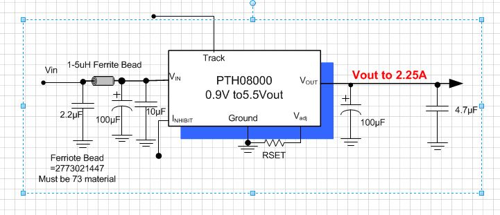
Is it ok to have the inductor between the required minimum 100uF cap and the regulators?
Will one 100uF cap work for 2 or more PTH08000Ws?
Thanks,
Chris