This thread has been locked.

If you have a related question, please click the "Ask a related question" button in the top right corner. The newly created question will be automatically linked to this question.

UCC28631 gate driver disabled

Other Parts Discussed in Thread: PMP9643, UCC28631

project details

input 60-201V line to line three phase at 30-106Hz 

Expected bulk DC voltage is 78-261Vdc

output 24Vdc at 2A

Primary side regulated off-line converter

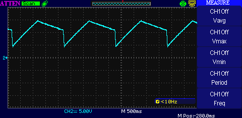
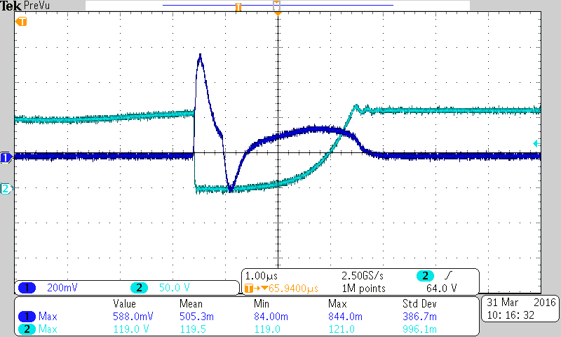
I made a schematic from PMP9643 and the Excel design calculator, which is below. The circuit board was layed out and prototype made. The prototype has been checked for connection errors. When connected to 100Vdc the VDD charges to 15v, then discharges to 11v, then plummets to 4v and starts all over again. see attached image for oscilloscope picture. The gate driver doesn't fire and seems to be disabled. Also the SD pin holds low despite the 19.1K oh resistance to ground at room temperature.

Why wont this chip fire the drive pin? Is the chip suitable for the input? 


APB flyback.pdf


  • Update: I open circuited the SD pin and i am now observing exploratory pulses. Bulk voltage during the testing was 150Vdc. unfortunately while moving the oscilloscope probe off the gate, the probe shorted the gate to drain and killed the mosfet and controller. Parts are on order. Any help is appreciated about how to go into full operation.
  • Hi David,

    I will forward your post to the apps engineer for this project, I would expect that you should see a reply tomorrow.

    Regards

    Peter
  • The SD pin must rise above Vtrip(rise) on startup for the IC to start. Nominally this is 3.5V, with a 210uA pull-up current. This equates to 16.66k of resistance on the pin, but taking tolerance into account, the resistance on the pin should be at least 20.54k to allow the IC to start. If the thermistor is 10k at room temperature the IC may not start.
    If the IC is giving three pulses but not starting up, it probably sees the bus voltage as being too low to start. Can you attach your excel calculator and I will check it.
    Thanks
    Billy
  • I added 31K to the 10K thermister to bring the SD pin to measured 4v. The bus voltage was 100Vdc during the screen shots and this is during the first and only three exploratory pulses.

    CH1 CS, CH2 DRV

    CH1 Vsense, CH2 DRV

    VDD during startup

    UCC28630 APC.zip

  • Hi David, per section 9.3.15 of the datasheet, the IC regulates the Vdd voltage between Vdd(latch_hi) and Vdd(latch_lo) in latched fault mode. The Vdd waveform indicates that the IC has entered latched fault mode.
    From table 4 the most likely causes are Vsense pin short, CS pin short, or DRV pin short. I see that you've halved the suggested CS resistance. This may result in the IC detecting a short on the pin.
    I would start by removing one of the CS resistors and see if this helps.

    Thanks
    Billy
  • I had come to the same conclusion also. So my post on March 30 with all the scope screen shots is only using one 0.240 ohm CS resistor.

  • Can you try it without R12?
  • The voltage on the CS pin during the switch on time should be a ramp driven by the increasing inductor current, but it looks like it's just a divided down version of the DRV voltage. This is the area I would look at.
    Hope this helps
    Thanks
    Billy
  • I was getting a false reading with the scope attached to the gate and the current sense resistor. embedded is the picture of the CS pin along with the VDS during exploratory. The chip is now doing constant exploratory pulses. The CS waveform is still distorted. So I pulled out the transformer and found the primary inductance to be 300% more then expected.  A new transformer is being made.

  • Ok cool. The FET also appears not to be staying on, so there does appear to be a board issue here. Hopefully when you put the new transformer in it will help.

    Billy

  • I received the corrected transformer today. I put the transformer in and check all the connections . I received exploratory pulses at my starting value of 100VDC bulk. It only put out 24VDC on the output at 117VDC bulk.

    I need the supply to start at 78VDC bulk or lower, what do I change to this chip, or do I need another 700V startup chip?

  • I received the corrected transformer. I put the transformer in and checked the circuit board. I turned on the power at 100VDC bulk and got exploratory pulses. I had to increase the bulk voltage to 117VDC to get my 24VDC output.

    What can I change to lower the startup to 78VDC bulk or lower? or which other 700V HV startup flyback chip should I use?
  • Hi David, sorry for the delay replying. You'll need to increase R6 to get it to start at a lower bulk voltage, probably to about 4.3k or so. Note that this will make the IC think the line voltage is higher than it is, hence the lower startup. But the IC also uses the measurement of line voltage for other functions such as compensating for peak current overshoot and calculating the constant current limit point. Increasing R6 will lower the constant current limit trip point and possibly introduce some extra ripple on the output.

    Hope this helps.
    Thanks
    Billy
  • I found that using 4.99K on R6 allows for startup at 70Vdc, that is good. When i cause a dip in bulk voltage down to 10Vdc, then back to 70Vdc with in 2 seconds it is fine. But the same dip over 5 seconds triggers the latch mode where the VDD pin circles between 8-10Vdc.  The power can not be easily cycled because it is industrial equipment. I dont see any under voltage latching conditions in the data sheet for the UCC28631.  What can I do to keep the chip auto-restarting?