This thread has been locked.

If you have a related question, please click the "Ask a related question" button in the top right corner. The newly created question will be automatically linked to this question.

TPS60110 start current

Other Parts Discussed in Thread: TPS60110, TPS60150

Hi all!  

   I'm using TPS60110 in my board to step up voltage from lithium battery to 5V.  Iout is around 90mA  and supply two isolated DCDC ROE0505 and one SP485 all bypass with 22uF MLCC 0805 cap.

After start time all works well. I can't understand what happens during start.

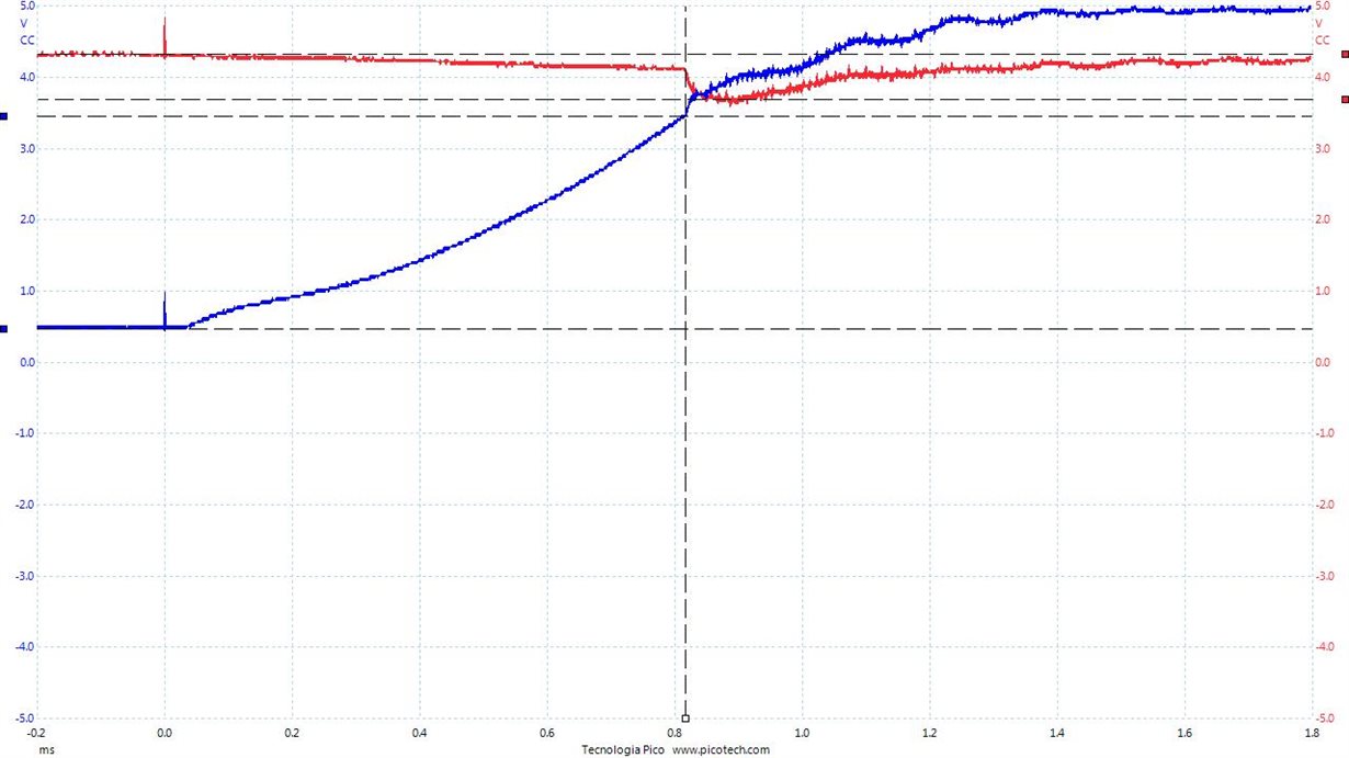
I execute some test only with TPS60110 and 22uF MLCC on output, NO LOAD. Below picture from oscilloscope.

In blue the ouput voltage of TPS60110 and in red the voltage after 300mOhm resistor between  voltage source of(4.39V) and TPS input. 
Trigger on enable rise edge. Time division 200uS/div.

So during voltage rise current follow it with ohmic law, until about 190mA, after happen an abrut current increase until 1.6A without LOAD. Can you explain why it happen? Who will use all that power?  Datasheet says that IoutMax should be 300 mA, without current protection circuit only with short protection. 

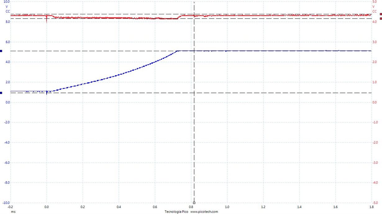
I try the same circuit with TPS60150 that expose soft start circuit with 150uS time rise. This is the result with FULL LOAD:

I expect an time rise of 150us but i measure 0.7us. Can you explain what happens? I think at start short protection circuit limit output current at 60/70 mA but that protection should disable after output rise of some volt, so why it don't delivery all current of 140mA what limit output current?

Thanks

Marco

  • Hi Marco,

    Did you use the TI evaluation boards for your tests?

    For the TPS60110 please have a look at the start-up description on page 11. The Device starts switching at ~ 3.5Vout in your application.

    How was your setup for the TPS60150 measurement? With higher load/output capacitance the softstart time could be longer than the typical value in the DS.

    Thanks & Regards,
    Michael
  • Thanks Michael,

    No, it's on my custom board.

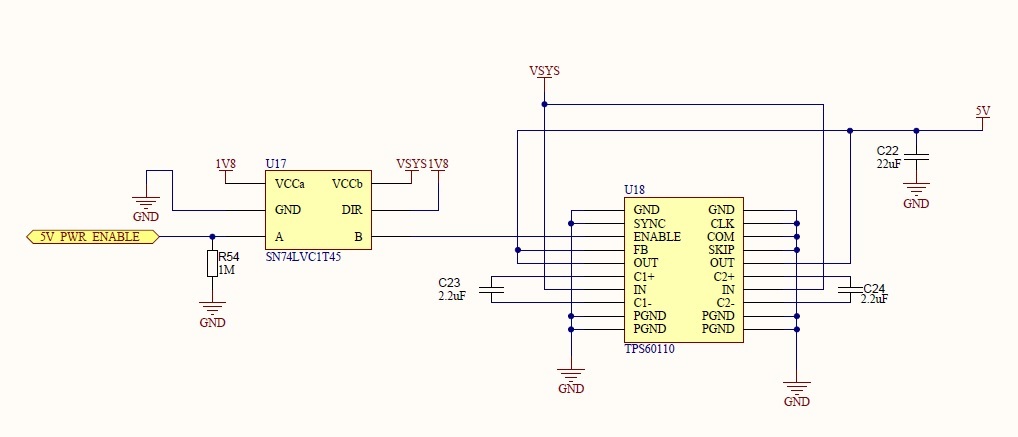
    This is schematics for TPS connection:

    Right, it's charge output at VIN less 2*Vds (or Vce) of internal switch, but it think it should be an RC charge curve because it put in series Vin with two equivalent resistance and capacitor C22. In oscilloscope red curve doesn't seems RC current. And why when it start to oscillate sink 1.6A and not limit to 300mA?

    For TPS60150 has similar schematics, what i would know if are there some way of know at prior that behavior and exstimate current and time or if unique solutions is try and see.

    Thanks

    Marco

  • Hi Marco,

    Do you have a capacitor on your TPS60110 input? I cannot see one on the schematic.

    Regards,
    Michael
  • Very near to chip there aren't caps, i know it is a mistake i'll correct in a new release, the chip is feed through a track with 1mm of width and two vias one from top to bottom e second viceversa. At start of this track there are C R C network 10uF 80mOhm (series power switch internal resistance) 100 nF.

    Measure of current are take before of these RCR network so it doesn't show inductive or resisteve loss o track.

    However i have to place huge cap to supply more than 1A.

    Thanks very much of support.

    Marco