Hi,
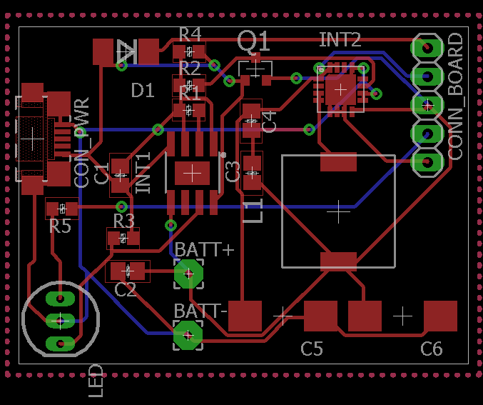
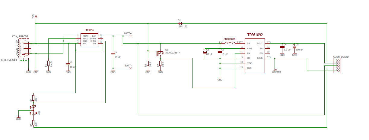
I have designed a boost regulator to generate 5V from a lipo battery (3.7V), the circuit can also recharge the battery and the TPS is disconnected when an external voltage (Max 5V) is connected. The problem is that after some days the TPS broke down (there is a short circuit between the SW pin and GND). The schematic seems OK and the max current that the load required is less then 1A so all should work well. I can't understand what is wrong maybe the layout is wrong. I take the 5V output between the pin 2 and 5 of the CONN_BOARD (The schematic and the layout are attached)., R3 and C6 aren't connected and the value of R2 and R4 is 2K .