This thread has been locked.

If you have a related question, please click the "Ask a related question" button in the top right corner. The newly created question will be automatically linked to this question.

TPS27081A Turn-ON Slew Rate Not Working

Other Parts Discussed in Thread: TPS55340, CC3200MOD, TPS27082L

I have this switch between my TPS55340 3.3V SEPIC converter and my CC3200MOD Wi-Fi module. I am trying to use it as a load switch so I can completely cut power off to the Wi-Fi module when it is not being used (95% of the time).

My issue comes when I try to run this board from alkaline batteries (4 in series to yield 6V). Due to the way alkaline batteries act the voltage drops when the current increases. When I enable the Wi-Fi switch it causes the battery voltage to droop below my 3V minimum input voltage threshold. This causes my device to reset.

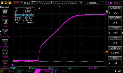
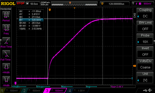
My assumption is the issue is due to the Wi-Fi's two 100uF capacitors trying to charge when the switch is enabled. My initial design had R2 grounded, but after discovering this issue I went back and added in a resistor between pin 1 (R2) and ground. It did not seem to help, so I began using the scope to inspect the rise time. Regardless of the resistor value I install (1K, 10K, 100K) it doesn't seem to make any difference in the rise time of my signal. 

My initial design has a 1MΩ for R1, but I have also tried the recommended 10KΩ resistor with the same results.

Below is the result with R2 pin grounded.

Below is the result with a 1K resistor.

The 10K and 100K are all essentially the same and it doesn't seem to matter if R1 is 10K or 1M.

It doesn't really matter in this application how long it take the Wi-Fi to start up (5 seconds would be OK), but I need to slow it down somehow because right now it is starting too fast and causing issues.

Why isn't my slew rate being effected and what can I do to resolve this? I would really appreciate some help on this.

P.S. An interesting side note is that if I enable the Wi-Fi switch first then then SEPIC it will start up OK (I'm assuming the SEPIC's soft start is allowing this). While this is nice to know, I need to be able to trigger the Wi-Fi on/off while keeping the SEPIC on.

  • Hi Kevin,

    The appropriate engineer has been contacted and will reply soon.

    Thanks,

    Alek Kaknevicius

  • Hello Kevin,

    From your schematic it looks like you don't have a capacitor between the R1/C1 pin and VOUT.
    This capacitor, in conjunction with R2, is part of configuring the turnon slew rate.
    Please refer to page 11 of the datasheet for more information.

    Best,
    Michael
  • Thank you. Sometimes it just takes that second set of eyes. I assumed the capacitor went to ground and that my C103 was what I needed. I now realize that the diagram is showing that capacitor running through the part body and out to the R1/C1 pin. I still think there is a better way to represent this in the image that may be more clear but I do understand now. I added in that capacitor and it worked as expected.

    I went with a 100K resistor and a 4700pF capacitor as when I used a larger capacitor there were voltage spikes on the output of the switch when power was applied to the input. Is this expected?

    Also, there is now a 180mV level on the output of the switch. Is there a way to get rid of this while maintaining the slew rate?
  • Kevin,

    I absolutely agree, I think it could be more clear in the diagram and will take this feedback for when we work to update the datasheet next time.

    When the supply turns on, typically if it has a high slew rate, it can actually turn the switch on momentarily. If this is an issue, I would recommend looking at the TPS27082L, which has an additional logic circuitry that prevents the switch from turning on.

    What are your R1 and R2 values? R1 should be > 10*R2 Is the capacitor fully discharging. I may actually have to look further into the offset on the output.

    Best,
    Michael
  • Michael,

    My values are as follows:

    R1: 1MΩ

    R2: 100KΩ

    C1: 1uF

  • Any follow up on the offset with the values I am using?

  • Kevin,

    My sincere apologies for the delay.

    I would recommend decreasing the size of your resistors, one to two decades, to help reduce the offset.
    For example, I would recommend decreasing the 1M to 100k, the 100k to 10k, and consequently increase C1 to 47nF to have slew rate be the same.

    Let me know if this works out, again, I apologize for the delay.

    Best,
    Michael
  • Michael,

    I have tried adjusting the values and it doesn't really seem to make much of a difference. I think the issue may be related to the circuit on the output side not having a way to dissipate the voltage. There is 200uF of input capacitance to my CC3200MOD (what I am using this switch to turn on/off) per the recommendation and it seems like after a certain voltage there just isn't a place for the voltage to discharge through. If I add a 10K resistor to ground from the line I can watch the voltage slowly discharge all the way to 0 after disabling the switch. I can implement this in my end application if I have to, but would prefer not to waste power like that if I don't need to. 

    Also, as further information, it seems like the voltage level is more commonly around 700mV (not the 180mV I mentioned above).

    Any thoughts or recommendations?

  • Kevin,

    Yes, in order to ensure the output goes low, there needs to be some discharge path on the output. Does the CC3200MOD not discharge this current at all or does it just end up taking a very long time with such a large input impedance?

    I understand your concern, typically the output load is able to dissipate this charge through R1, C1, and the load resistance.

    Best,
    Michael
  • It is kind of odd because if we disable the switch the power drops to about 1V pretty quickly then seems to drain down to about 700mV after a couple seconds, but then it seems to just sit at that level. I haven't left it for an extended period to confirm, but once it hits the 700mV mark it seems pretty stable.

    The interesting part is if I remove power to the entire board the voltage drops to 0 almost instantly. I'm not sure what path is being used to drain power when the entire board is powered off that isn't available when only the switch is triggered.

    Here is my schematic for that section of my design if it helps.

  • Kevin,

    I have set up something similar on the bench to what you have and I found the following.
    What I did find is that with a 200uF output capacitance and a very high load resistance on the output there isnt a good path to discharge and I am actually finding that it stays charged up to the input voltage unless I put some sort of load on it.
    If I put a 100k load, it discharges but very slowly (>30s), and it does seem to settle somewhere around 100 to 200mV.

    When you say you remove power, are you actually disconnecting the power or are you setting the Vin = 0V. I found that disconnecting the supply makes it so that it still discharges very slowly, but setting the input voltage to 0 discharges it rapidly.

    I think that the output needs a better path to discharge to ensure that it is 0V. I hope this helps.

    Best,
    Michael
  • Michael,

    When I say I remove power I am taking the battery off my system. However, this battery is run through a 3.3V SEPIC converter before going to the switch, so I'm not exactly sure how that would change things. I wouldn't guess that it drives the input to 0, but maybe it does. Anyways, I think I'm going to just put the output load resistor there to drain that off.

    Thanks again for all the help you have provided on these issues.
  • Kevin,

    Always happy to help.
    Please let me know if you have additional questions.

    Best,
    Michael