This thread has been locked.

If you have a related question, please click the "Ask a related question" button in the top right corner. The newly created question will be automatically linked to this question.

TPS54339 Input side tantalum capacitor blows when 5V is applied to output

Other Parts Discussed in Thread: TPS54339

Hi

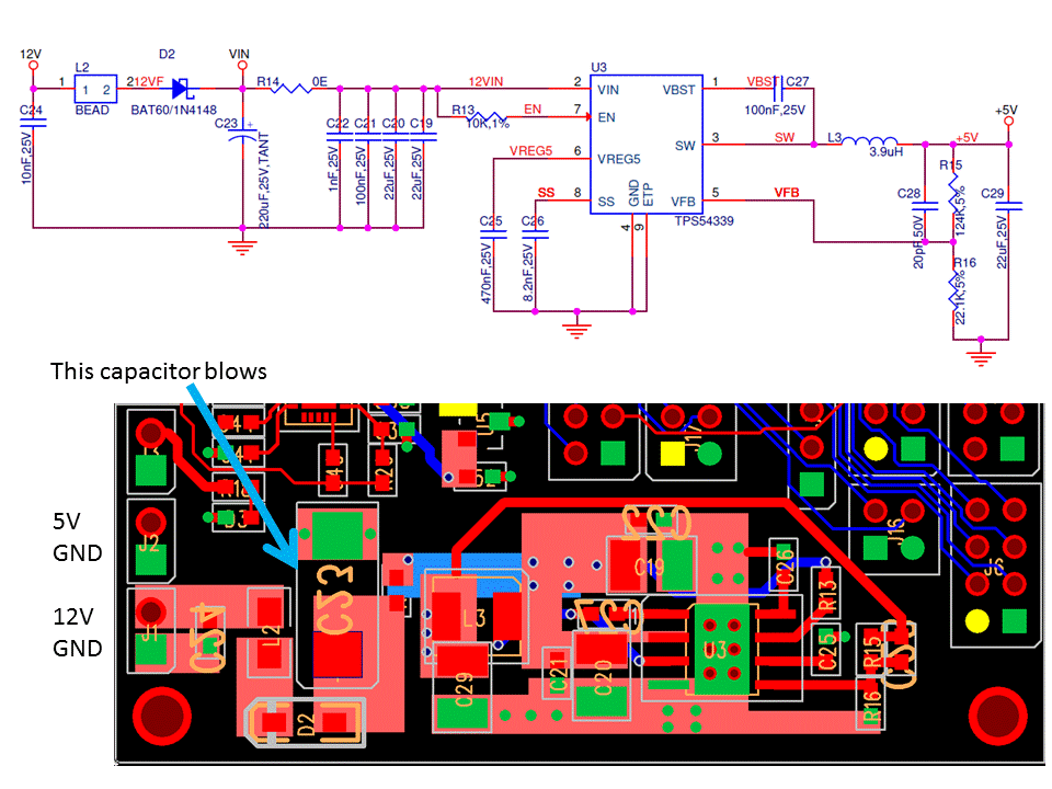
I am using TPS54339 for converting 12V supply to 5V. Circuit has options for both 5V and 12V input power connectors. 5V connector is connected to output of TPS54339 after inductor. Circuit performs without any issue at 12V. At 5V, circuit performed without any issue but at random times, a 220uF tantalum capacitor placed at the 12V input of TPS54339 blows. There is no other damage to the circuit apart from this capacitor and once this cap is removed, circuit works find without any other part being touched. There is a protection diode (used 1N4148 ) before the capacitor in case there are some surges in 12V.

This happened on 4 different boards and same behavior was observed. I could not find any explanation of this tantalum cap catching fire when there is no direct Power. Please suggest what rework/modification can be applied to prevent further damages.

Regards,

Fahd 

  • Can you post your schematic and layout?

  • Hi John,

    I have attached image of both schematic and layout section of TPS54339 for your perusal.

    I  have verified that connection at 5V connector was correct and there was nothing at 12V connector when the cap blew.

  • When tantalum caps blow, it is almost always because of over voltage. If you are applying an external 5 V, you may be accidentally boosting up the input. Check to see if the IC is switching at SW and what the input voltage is going to.
  • Hi John,

    I tested our boards with a 5V power bank (used for mobile charging) with rating of 3000mAh. Below are the observations

    * Input voltage reaches up to 26.5V at power up. It remains at this high value for around 2 seconds and then decreases to 5.8V. out of 5 iterations, it once reached 26.5V, and for other 4 times, it was between 18V to 21 V (that pretty much explains to me why tantalum cap blew, it rated 25V)

    * Voltage at SW pin was surprising. At power up it reaches around 150V and stays there for around 4 to 5 seconds and then comes down to 4 to 4.4V. I repeated this test with different multimeters but it reaches 150V and once went beyond 200V irrespective of DMM used. Not sure why this happened and looking for explanation for this.

    Would like your guidance on how to tackle this

  • When voltage is applied to the output with no input supply, the high side FET body diode can conduct and voltage appears on the input.. If it is high enough to turn on the IC, the TPS54339 can act as a boost converter and boost up the input to uncontrolled voltages. This is not unique to TPS54339, but is common to most synchronous buck converters. You may try adding a diode in series with the output to block current when you apply voltage on the output with no input.