This thread has been locked.

If you have a related question, please click the "Ask a related question" button in the top right corner. The newly created question will be automatically linked to this question.

LM2735Y draws high input current when hot

Other Parts Discussed in Thread: LM2735

I have an issue with an application for an LM2735Y.

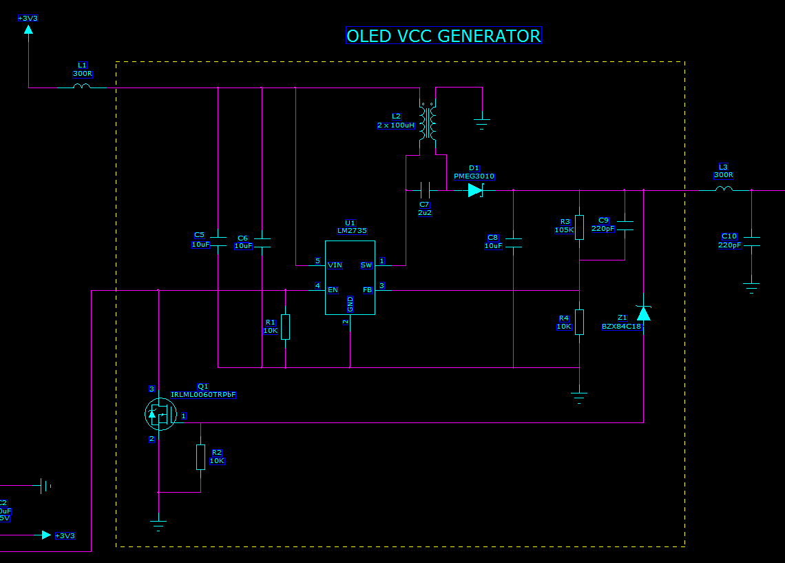
This boost regulator chip is being used in SEPIC mode to step up from 3.3V to 14.5V to drive an OLED supply voltage. The circuit works fine most of the time but when I increase the temperature the circuit goes into runaway at about 86°C. To eliminate the OLED from the equation I have replaced this with a resistive load of 500R (load current = 29mA). With this fixed output load the input current slowly increases (from the ambient temperature value of approximately 146mA) with temperature. At about 75°C (about 176mA) this rate of change increases until at 86°C it takes off so the input current exceeds 500mA and the supply collapses.

The circuit needs to operate in high temperatures and although 86C is beyond our working range it is bit too close to the upper limit for comfort.

The circuit was designed with a dual coil choke of 2 x 1mH. As this inductance is a bit high compared to Ti recommendations I have reduced this to 22µH and 10µH without any change in the overall result.

 The chokes are Wurth parts, for example the 22µH part is 744 877 220 and the 10µH part is 744 871 100.

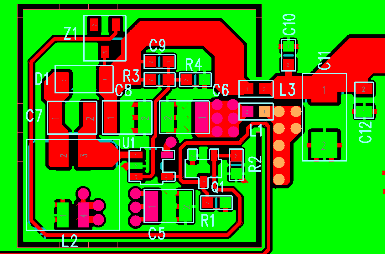
The parts are mounted on a PCB and closely coupled so I do not think layout has any influence.

 Heating up each component in turn suggests that the series coupling capacitor  or output capacitor  may be the cause of the problem. These are ceramic parts from AVX, 12105C225KAT2A and 12103C106KAT2A respectively. I have contacted AVX for details of ripple current and ESR variation with temperature. However if I halve the output load, even though the input current is reduced (79mA at ambient temperature), the runaway occurs at the same temperature as before. So the effect does not appear to be load related.

Also, thinking that the effect may be due to too much ripple current in either capacitor, I doubled up on both of these, again with no effect.

Curiously the system duty cycle does not seem to vary very much with temperature or load, being about 82% (i.e. LM2735 MOSFET mainly on).

Any suggestions would be helpful. So far nothing I have tried makes any difference. It is worth mentioning that the runaway temperature is pretty consistent, no matter what I try.Thanks.

  • Hi Ian ,

    Can you please forward the complete schematic of the design .
    Also when say 86C , you are talking about ambient temperature. Right?

    --Ambreesh
  • Hello Ambreesh,

    Yes 86C is the ambient temperature. I appreciate this is a bit hot. That said, at ambient temperature the surface temperature of the components only rises by 2or 3 degrees .

    Schematic is below as is the PCB layout (component layer only) and a plot of input current and 1-Duty cycle against ambient temperature.

    1-D is measured with an oscilloscope at pin 1 of U1.

    L1 and L3 are ferrite beads. 300R is their impedance at 100MHz, not their resistance. 

    As mentioned in my original question different values of L2, C7 and C8 and output load have been tried but have no effect on the input current variation.

    Z1 and Q1 protect against o/p overvoltage and are not coming into play.

    a 10uF tantalum reservoir capacitor is fitted after L3 (not shown).

    For this test the enable input is pulled high via a 1kR resistor to 3V3 (not shown).

    The OLED display load has been replaced with 500R or 1kR (not shown) for the purpose of this investigation.

    Thanks for your help.


  • Hi Ian ,

    At 3.3Vinput and 14.5V @ 30mA output(10uH coupled inductor ) , the design loop is unstable . Changing the Cff C9 to  2.2nF would make the loop stable .

    I did the simulation based on your design and found that the design is unstable with phase margin of 10 degrees with Cff of 220pF . Addong a zero(with Cff=2.2nF) before the crossover resulted in phase boost and hence >60 degree of phase margin .

    Can you replace the Cff and re do your thermal test . As mentioned ablove , please use 10uH coupled inductance .

    With Best Regards

    Ambreesh

  • Hello Ambreesh,

    Many thanks for your reply. I did notice some occasional instability when I tried the 10uH choke but this was oversize for the PCB layout so I had assumed (obviously wrongly) that it was down to having the choke on short flying leads. I have not noticed any sign of instability with 22uH or 1mH but I will have to look out for the design tool and check this. I am out of the office for the next week so it will take a while before I can confirm your suggestion solves the issue. Thanks again.

    Ian


  • Hello Ambreesh,

    Apologies for being quiet on this, have been busy with other things. Have now solved the issue. I noticed that the reverse leakage specification at temperature for the catch diode was a bit on the high side so have replaced it with a part with lower leakage (and a bit more bulk to dissipate any power generated by the reverse leakage). The input current now remains stable all the way up to 96C at which point I terminated the test. This is true both for my test set up and the actual application. Thanks for your help with this though. Also could you let me know which package you used to determine system stability? Thanks.


    Ian

  • Hi Ian,

    I did the simulation based on 550KHz of switching (Y version).

    ---Ambreesh