This thread has been locked.

If you have a related question, please click the "Ask a related question" button in the top right corner. The newly created question will be automatically linked to this question.

UCC2863x fault cause codes

Other Parts Discussed in Thread: UCC28630

Greetings,


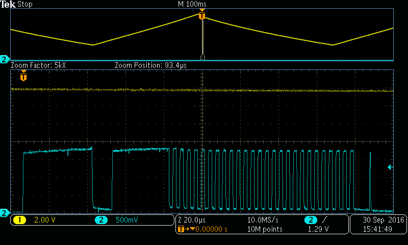
I have rebuilt a power supply based on the UCC28631, creating several supplies based on working prototypes with modifications from this post.  However, I am having trouble with startup again, after tweaking values for optimal performance.  I read the fault-code pulse train at the SD pin as described in the previously mentioned post, copied below

I would recommend that you probe the SD pin (pin 2) of the UCC28631 after the latched fault has tripped (the region where VDD is regulated between ~ 8-10 V). Every time VDD hits the upper level ~ 10 V, the fault cause is detectable by a pulse train on the SD pin.

The fault-code pulse train starts with a ~30-us positive pulse (start-pulse - can used for scope trigger), then a train of ~1-us positive pulses, then a low interval of ~10 us to signify end of the pulse train. Count the number of 1-us pulses in between the start/end.

The possible faults in this case are as follows:
21 - VSENSE pin fault - short, or open detected, or Rth out of range
22 - DRV pin fault - short detected
23 - CS pin fault - short or open detected

However, code I read was 26, and there was an extra 30us pulse before the fault code train.  Is there a full list of codes someplace, and is the extra 30us pulse start significant?


CH1: Vdd     CH2: SD pin, past resistor

SD code read at node between 8.87k resistor [to SD pin] and 10k thermistor (to ground)

Thank you,

  • Hello Patrick,
    I will alert the appropriate engineering staff to address your questions.
    Regards,
    Ulrich
  • Patrick

    The 30 us pulse is already described in the text above - it's a preamable pulse that can be used for triggering. There is also a deliberate 10-us low interval at the end of the pulse train to signify that it has ended. It's the short 1-us positive pulses in between that give the code.

    As you noted, in this case it's 26 - this is external over-temperature, or SD pin fault, i.e. the SD pin is externally pulled below the trip threshold.

    At startup, and for recovery from a prior over-temperature event, the pin must pull-up to > 3.8 V worst case, 3.5 V nominal. This hysteresis to the falling trip threshold of 2.0 V ensures some off-time for the temperature to drop after a fault occurs. With the internal pull-up of 210 uA (or 185 uA min worst case), this means the external impedance must be > 20.5 k-ohm to allow startup or restart.

    Above you note that the SD pin has 8.87 k-ohm in series with 10-k NTC, nominally this should just about get over the start threshold, but not worst case. I think it may be very marginal.

    I would suggest opening the NTC temporarily to see if the problem goes away. If so, then I would recommend using an NTC part with higher impedance, and then drop the series resistance as required to tune the trip temperature. The SD pin will nominally trip for overtemperature when the pin drops to 2 V, which is a total net resistance of ~10 k.

    The fault codes are there for internal dedug and testing, but here is the list of useful codes that may be relevant for system level debug:

    4 - VDD overvoltage
    5 - VDD undervoltage
    12 - overlaod timer time-out - only for UCC28630
    14 - AC (i.e. bulk cap level) under-voltage detection while running
    15 - overtemperature internal (die temp)
    18 - SD pin fault
    20 - output overvoltage
    21 - VSENSE pin fault
    22 - DRV pin fault
    23 - CS pin fault
    24 - X-cap discharge event triggered - only for UCC28630/3
    25 - AC (i.e. bulk cap level) under-voltage detection before startup or restart
    26 - external overtemperature fault (SD pin pulled low)


    I hope this helps get you going again.

    If this answers your question, please click the "verify answer" button.

    Thanks,
    Bernard
  • Thank you for that answer.

    Depopulating the resistor for the SD pin (opening SD) allowed startup. Now to redesign the thermistor sense circuit to allow correct operation.