This thread has been locked.

If you have a related question, please click the "Ask a related question" button in the top right corner. The newly created question will be automatically linked to this question.

LM43600 duty cycle not increasing under load

Other Parts Discussed in Thread: LM43600

Hello,

I've recently changed my buck switching regulator to an LM43600.  The issue I'm having is that it doesn't seem to increase the duty cycle under load.  I'm kicking of a Tiva Arm and ADC and this transient is dragging down my 3.3V rail by 20mV.  This is causing a voltage drop in the VCC of the analog filters that are also powered by 3.3V.  I can see it in my data and with amplification is very bad.   It goes back up 20mV and returns to normal when I'm done sampling etc...it just tracks the burst of sampling and the processor.

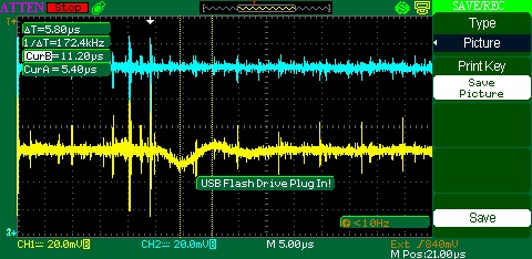
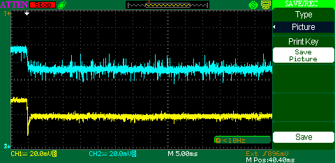
Here is a pic of my voltage rail drop:

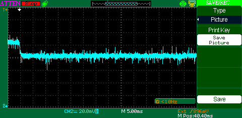
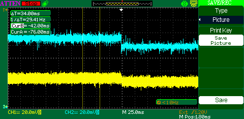
Here is a screen shot of the output voltage tracking the feedback pin on the eval board.  It just sits down for an extended period of time.  Blue rail is Vcc (output of the LM43600...same as above.  Bottom/Yellow trace is the feedback pin of the regulator.  The probe was placed on the eval board between resistors Rfbb and Rfbt)

When I look at the duty cycle of the switch it looks like it just sits around 50%, in fact 50% exactly.  I'm using the LM43600 evaluation module from TI and i haven't modified it so it is running at 500kHz.  The data sheet said the part has a Toff min of 250nS.  I would think this part would try to correct for this drop.  I lose 20mV on Vcc for the amount of time I'm sampling.  Basically, it looks like if I attach a load I get this long voltage drop.  I've tested it up to 300mS which is more than enough time to recover. 


I'm powering the LM43600 evaluation card with a bench top supply set to 8V at 0.5A. 

Here is the link that shows the card and the schematics.

www.ti.com/.../snvu424.pdf

I'm not an analog/PS designer but usually the pulse width just increases to maintain a steady voltage even if there is a transient like this. 

  • If you are going from no load to full load, then the slight drop in the output voltage is normal for the type of no-load architecture used in this device.  Please see the vout regulation curves in the data sheet.

    Also, be sure that you are measuring the output voltage at the regulator; your may have a drop in your connecting leads.

    If you need the extra 20mV at full load, you can adjust the output voltage up slightly with the feedback divider.

  • Hey thanks for the reply! That's not terrible news,but the problem for me is that transient. The output of the lm43600 supplies and ldo that has a drop out of 90mV. This is another time part. The ldo feeds my amps and filterse and this dip as well as the transient response is coupling into the LDO supply and therefore my analog circuitry. I think I am violating the 90mV min drop out voltage of the LDO because I haven't adjusted that evaluation card to out put a little higher voltage.

    With all that said though, do you have any recommendations on how to isolate these two supplies. The memory chips I write to produce some noise on the switcher output that also couples into my analog stuff. When I apply gains I can see it in my data.

    Any recommendations?
  • You could use a post LDO for the analog stuff.  However, as you mentioned, to get the best performance from the LDO you need to have enough head room at the LDO input.

  • Hey Frank thanks for the responses!

    So I've done what you said and it is actually running great with the exception of one small detail.  I have all of my analog stuff on on power plane fed by the LDO.  The problem is when the gain is turned up I get a dip on the analog (LDO output) power plane when I kick off the ADC and memory writes.

    The yellow trace shows the dip.  It isn't very big and the part recovers quick, but it does affect my amps and filters and therefore my data.  This is only prevalent when the amps are turned up to their higher gain which is a gain of 100.  Not unreasonable.  It is very small but with the gain it is present in my data.  There is a small noticeable dip. 

    I've tried adding ~100uF of bulk capacitance to this power plane and it doesn't seem to do much.  Does anyone have any advice?  I figure this can't be too uncommon.

    Here is a screen shot:

    You can see in the beginning the top two channels dip, then come back up.  I'm thinking this is because of that transient.  It matches up to it as they are both right at the beginning.  I know transients like this are part of the game, but how do people handle kicking off ADCs and what not, but still preserve the integrity of the information coming into the circuit?  Do I just need massive bulk capacitance?

    Thanks!

  • You could try an LC or RC filter on the analog power line; using just a cap may not be effective because of the low impedance of the power plane.

  • Wold I be putting the LC power filter in series with each amp''s power pin so that each vcc pin on each amp has has a large cap with an inductor in series with power?  

    Or could I just put an inductor at the output of the refulator?

    Does the inductor in a way "force" the amps to use the bulk capacitance rather than the power plane?

  • You might try just one common filter. You will have to experiment. 

    Yes, your explanation is correct.

  • Hey Frank,

    I have been working on this and implemented some filters.  I haven't had any luck but I was wondering what you thought about this new clue.  I have disconnected my signal generator OUTPUT from the device and connected it directly to an O'scope probe with nothing else attached.  The GROUND of the signal generator is tied into the device as well as tied into the O'scope.  Basically everything is grounded through my device (O'scope and signal generator) but I disconnected the output of the signal generator so instead of it connecting to the input channel of the data recorder it is connected directly to the Oscope.

    Upon running this same test I see that with ONLY the GROUNDS connected I get a dip in the signal generator output.  Shown Below:

    The top trace shows my unregulated Vcc power rail which makes sense.  This is what takes a hit and drops ~20mV and stays there until I'm done running the ADC which we talked about above being normal for the switching regulator.  I have this trace captured to show when the event starts.  The bottom trace (yellow) shows the out put of the signal generator which is only connected to the device by a common ground.  The out put is connected ONLY to the Oscope channel. 

    Does this mean I need to isolate my grounds as well as the power planes?  Do I have a ground shift issue?  I feel like it has to be related to everything being grounded together because  the output of a signal B&K sign gen is dropping as soon as I kick off the ADC.  This is causing my problem in the above plotted data file because the channel inputs were AC coupled.