This thread has been locked.

If you have a related question, please click the "Ask a related question" button in the top right corner. The newly created question will be automatically linked to this question.

problem in working with Li-ion battery charging IC BQ24170

Other Parts Discussed in Thread: CSD15571Q2, BQ24170

Hi,

I followed the sluu463 EVM schematic for the battery charging IC, I changed the some of the components in the schematic as I don't have that  components right now, the changed components are as follows

Q2,Q3= CSD15571Q2

D3=1N589

D2=MBR360

R2,R15= Replaced with short

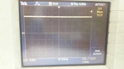
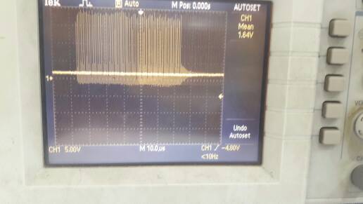
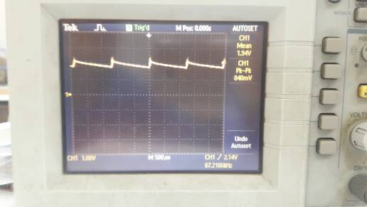
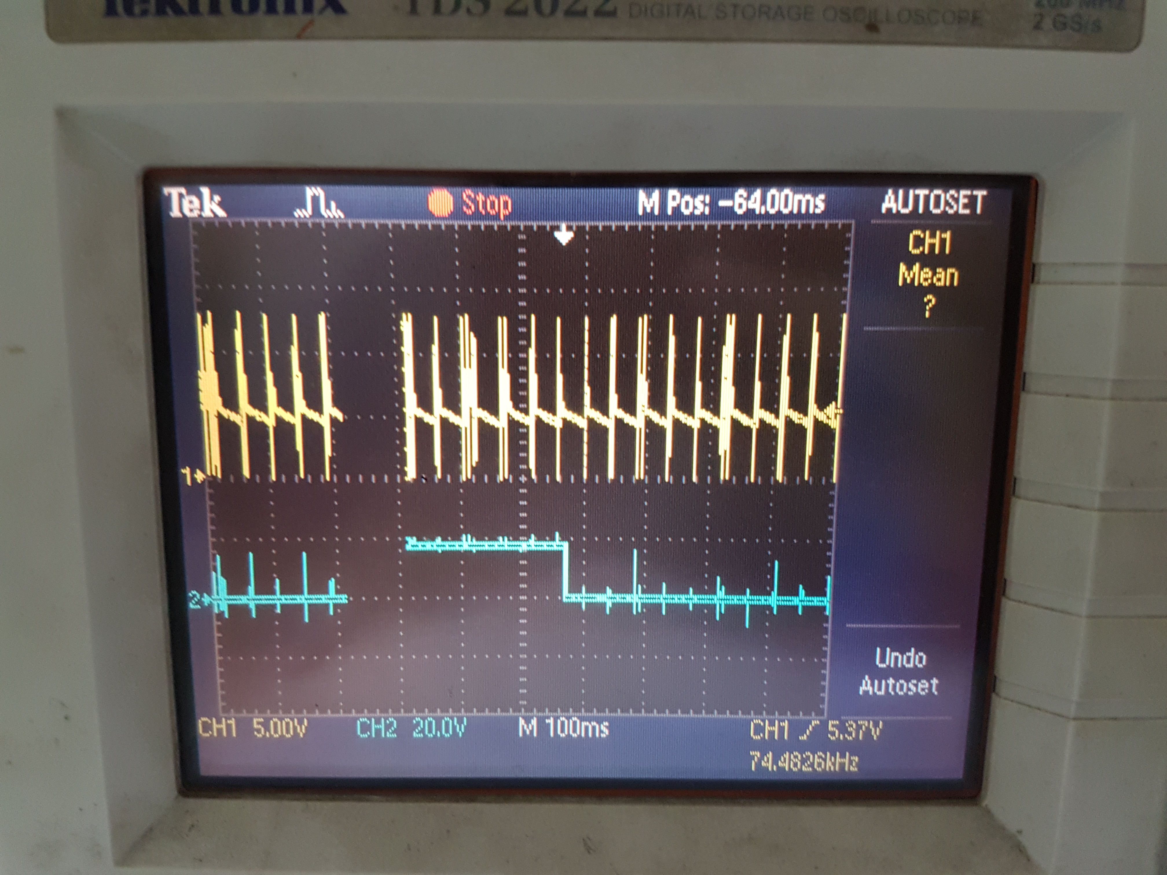
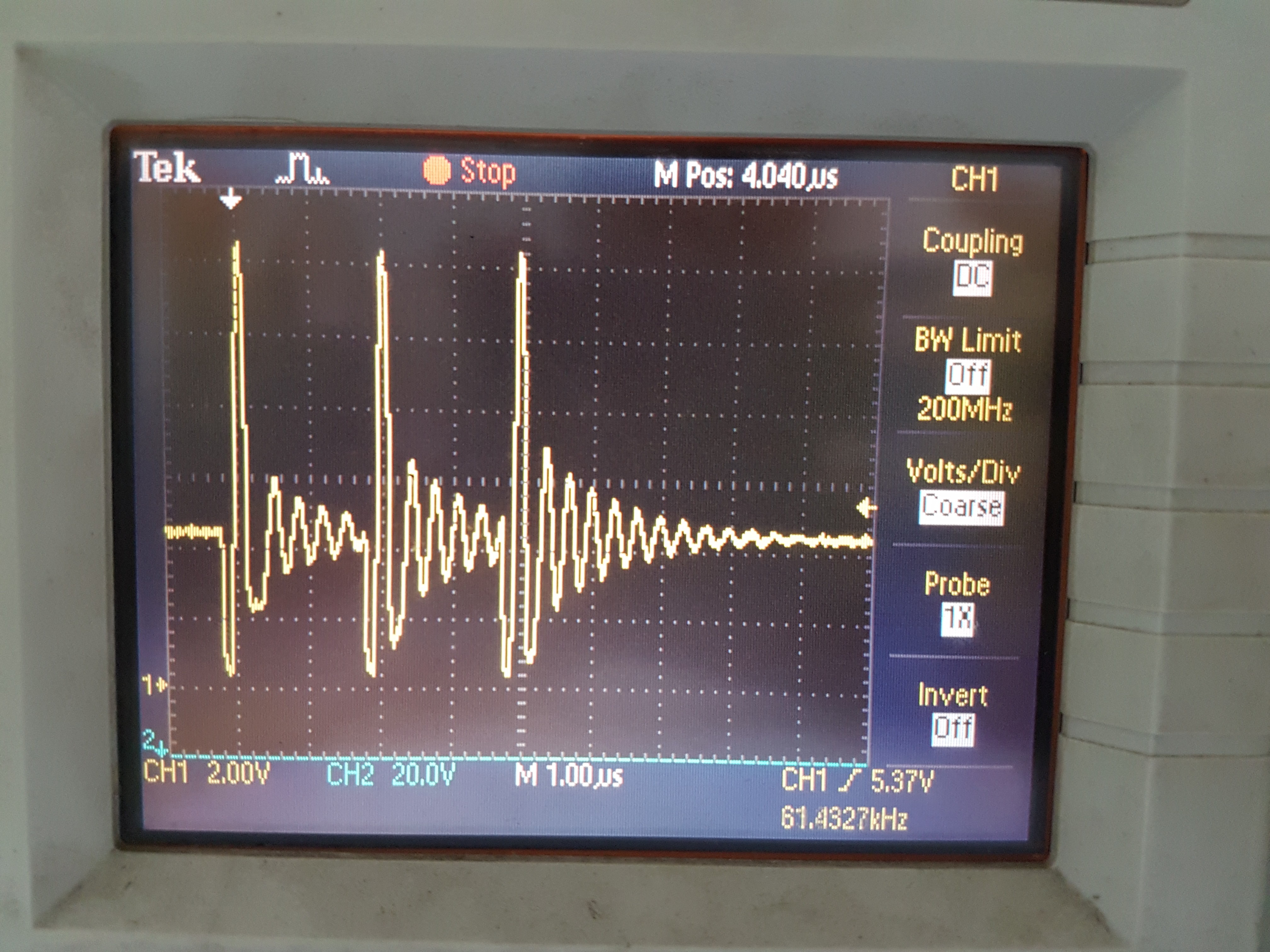
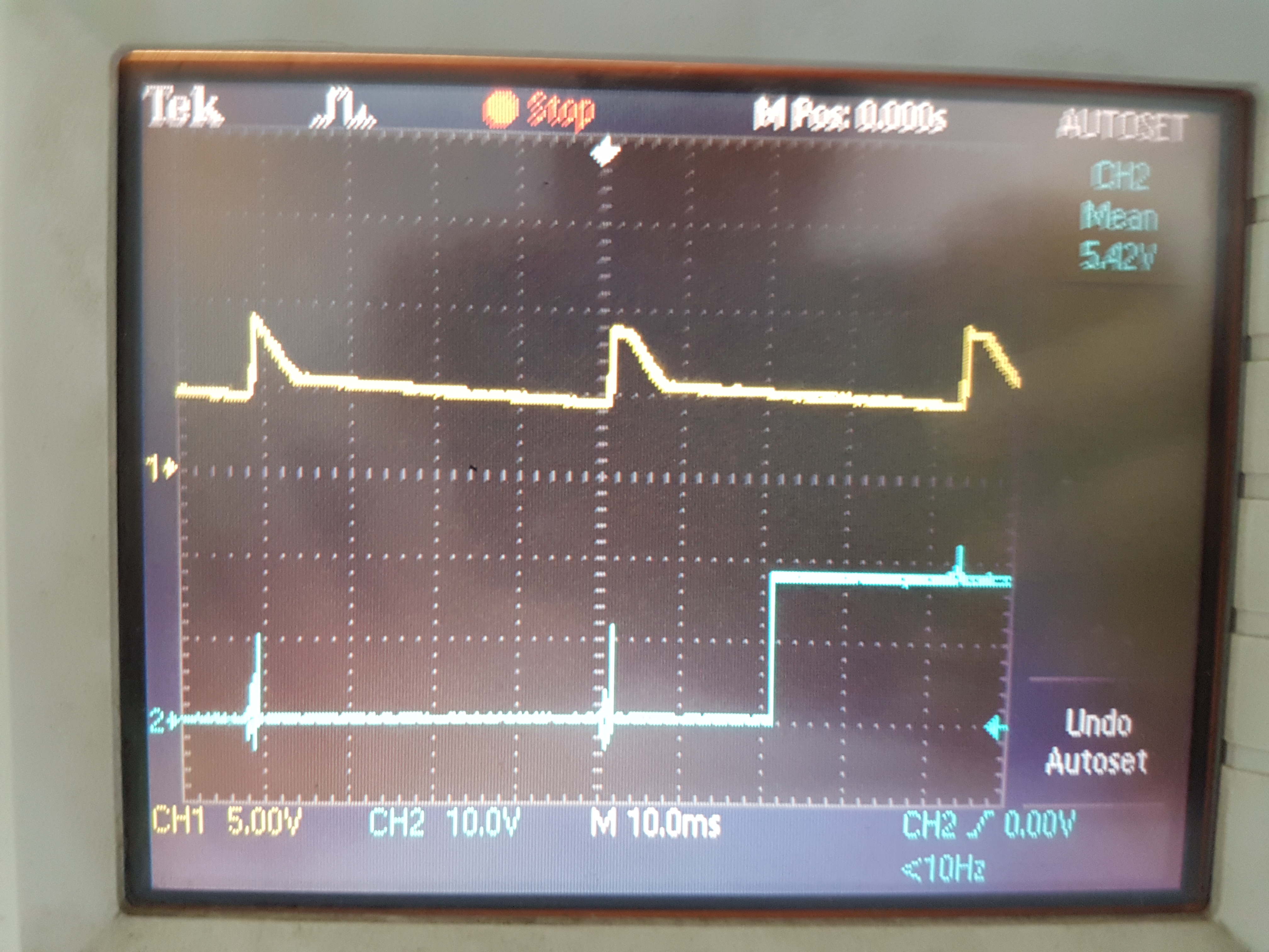
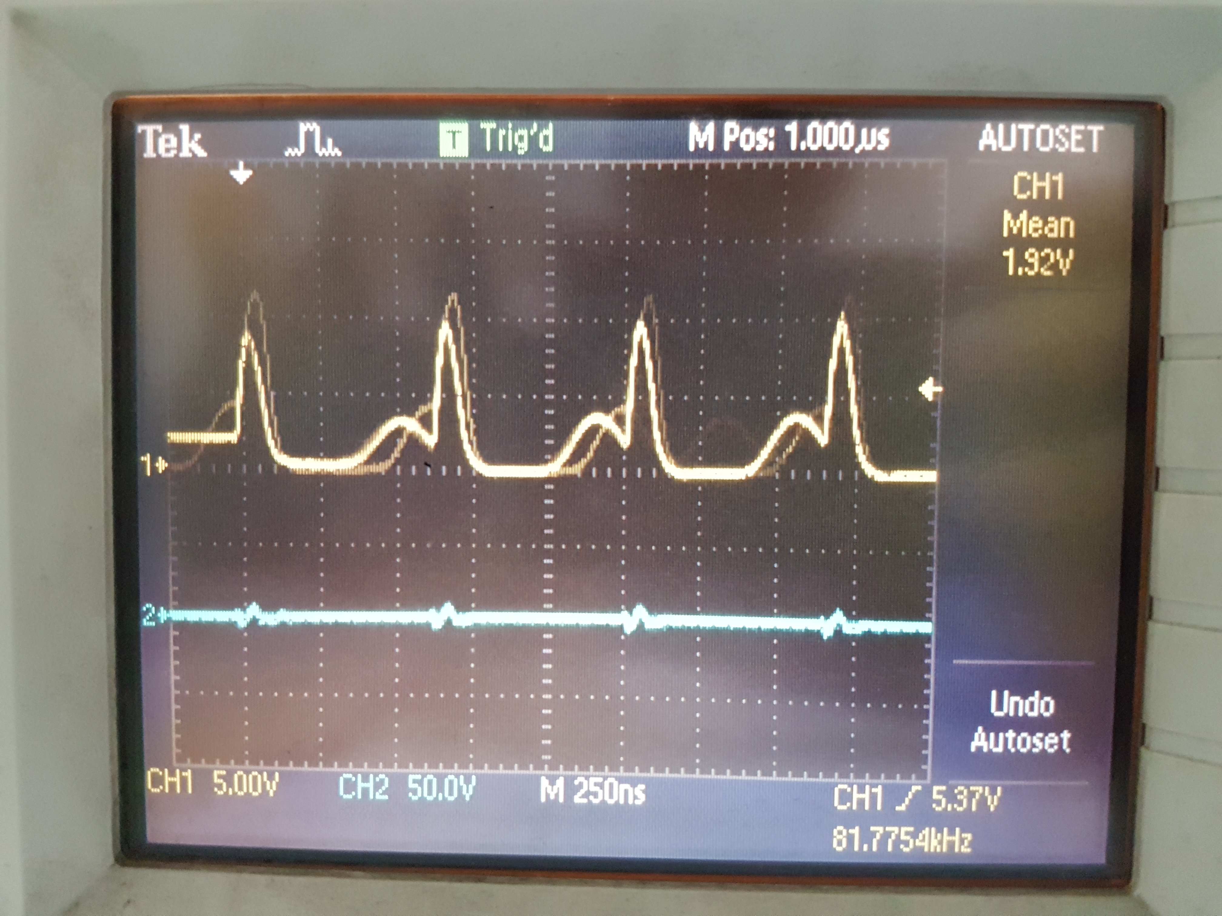
I checked the status pin,it is showing always 3.6V, I'm not able to understand what is the problem in the circuit. Except the above changes everything is same I followed. Please someone help me to find out the mistake.

  • Hi Dhananjay,

    It seems like you are working with Noel on this project, who I just responded too. I will give you the same reply below, plus one more comment.

    A quick comment on your FET selection - I looked at the one you guys choose. For the ACFETs (or blocking FETs, whichever you prefer to call them), they do not switch very frequently. Therefore, choosing a FET with ~ 2nC of Qgd will not be very beneficial when if they have a high-ish RDSon (you have ~20mOhms). The blocking FETs will almost always be on during charging, so most of your losses will come from conduction (RDSon) losses rather than switching (Qg) losses. If you are really worried about efficiency/thermal, then you may want to find a FET with lower RDSon. That being said, 20mOhm's most likely won't ruin your design.

    Here is the reply I gave Noel:

    Hi Noel,
    When the STAT pin is always high (3.6V), this indicates that the charger is either in sleep mode (Vbat > VCC - ~0.2V), or that charge is complete. Since you shorted R15, I am guessing that the charger believes that charge is complete.
    R15 is used to set the charge current in the circuit, as well as in the charge current regulation loop. The charger will read 20*the voltage across R15 and compare that to the ISET voltage, and manipulate the converter gate drives from there. Right now it looks like the charger reads 0 voltage drop from SRP to SRN, and "thinks" that charge is complete.
    Try placing a sense resistor there, and it should work.
  • Hi David,

    Thanks for the reply.

     We attached the current sensing resisters too, still the circuit is not working. I uploaded my circuit diagram please check and let me know the problem with the circuit.

    in the circuit CE is grounded and TTC too grounded, and most of the capacitors I used in the circuit are electrolytic rather than ceramic, will that make any difference?, Status pin is always high in the circuit.

    The voltages on the IC pins are as follows:

     ISET       =370mV

     OVPSET=1V

    VREF       =3.3V

    REGN      =0V

    TS             =1.94V

    ACDRV   =17.4V

    AVCC      =12.4V

    CMSRC  =12.4V

    BATDRV =12.4V

    SW          =0V

    VSYS      =12.4V

  • Dhananjay,

    No problem...thanks for uploading the  schematic!

    If you are using electrolytics, I think it will be okay as along as the ESR is low enough. The reason we want ceramic caps is because of their low ESR. The  output cap's ESR effects the buck converters transfer function by changing the frequency of a zero.I don't think this is an issue here,though. If it was you would likely see oscillations or poor load transient response.

    I think I see the problem - can you measure battery voltage  (SRN pin) and AVCC for me please? My guess  is that R22 is creating a voltage divider with the 10 ohm resistor at AVCC, which is causing the bq24170 to be in sleep mode. If you remove R22, I think everything will work fine.

  • David,

    I edited my previous post with the voltages on all the IC pins please find it.
    thank you.

    Dhananjay
  • Thanks for updating the post with the voltages - it looks like a problem with REGN. REGN is used to bias the high side FET gate drive. If that LDO is shot or overloaded, switching won't be enabled.

    Try removing R22 , C7,C8, and D2 ( this circuit seems unnecessary, unless there is something I am missing) and seeing if REGN comes back. If REGN is still at 0V, try replacing the IC with these modifications.
  • David,

    After removing the resistance R22 and capacitors C7, C8 and the diode D2 also the charger IC didn't work. So I changed the IC and then checked, found the LED keeps on blinking and now REGN pin is giving the 6V but VBAT giving the voltage around 1.7V and even after connecting my battery to the VBAT,  LED keeps on blinking.

    Regards,

    Dhananjay J

  • Dhananjay,

    That means your last IC was fried. If STAT is blinking, we now have something to work with.

    That is interesting that Vbat is only 1.7V. Let's do this:

    Can you repeat the DC measurements? I would like to see what happens when your battery is attached. The voltage at PVCC will be important - if that is ~Vin, then there is a problem with the converter.

    Can you check to make sure the inductor isn't shorted?

    What is the ESR of your output caps? If it is high enough, the control loop may be unstable. Do you have a low ESR cap that you can put in parallel?

    Without a battery, is your circuit running the battery detection function?

    If you can, scope traces of PVCC, SW, and Vbat would also be helpful
  • Hi David,

    If I connect the battery the LED starts blinking, if I remove the battery LED keeps on glowing.

    without battery connected the voltages at pins PVCC =12V,

                                                                                        SW     =1.7V,

                                                                                       VBAT  =1.7v,

    When battery connected the voltages at the pin PVCC is 12.2V

    At the pin SW is shown below


    At pin VBAT is 1.94V

    and the remaining pins are same in both the instances as ISET=400mv, VREF=3.3V, REGN=6V, TS=1.9V.

    * Inductor is not shorted, and I don't have any idea about the ESR of the capacitors, Because I don't have the datasheets of the capacitors I used, sorry .

  • Dhananjay,

    A couple comments:

    Can you retake the switching waveform with only one or two periods please? I should have specified this in my previous post. With a switching frequency of 1.6 MHz, there will not be much information gained from a 10us/division scale.

    Also, the mean value of the SW node does not mean much. That's exactly what it is - the mean of the switching waveform (a square wave). Passing a high frequency square wave (switching waveform) through an appropriately sized low pass filter (the LC circuit of the buck converter) will give you almost exactly the same thing. This is why is matches the battery voltage.

    What is really interesting is that it seems like the charger is recognizing a fault with the battery inserted (very possible), and that there is charging when the battery is removed. Given that there is no battery, nothing should be getting charged up.

    This makes me think that there may be a problem with the physical circuit, or that there is a problem with the converter (a better look at SW node will help this). If you look at your caps, there is a good chance of there being a part number on them. You can probably hunt down the datasheet that way, or asking whoever you got them from.

    So now, let's try a couple things:

    Can I get a better look at the SW node? If you can put battery voltage and STAT pin on the same plot, that would be helpful.

    Can you send me a picture of your board/ board layout? How did you put the charger IC on? There may be some shorts/soldering issues.

    In your schematic, it looked like you had a resistor in series with the BTST cap. Is that in the physical circuit? I would remove this if it is.

    If you want a quick "why not, let's see what happens" type of fix, find a couple ceramic caps (C value doesn't really matter, just low ESR and appropiate voltage rating) and put them in parallel with your output caps. This will reduce the total output ESR.
  • David,

    Hi,

    I had forgotten to inform you that when I switch the circuit on (without the battery), the LED blinks for sometime and if left undisturbed stays ON continuously until a battery is attached. I have made a set of two images of the SW, VBat and STAT pins while the LED binks and while stable.

    I have attached pictures relating to what you have requested. They follow bellow.

    Note: Channel 2 voltage is not correct. The STAT pin is Pulled up to Vref(3.3V) trough a 1.5K ohm resistor.

    The SW and STAT (Blinking)

    The SW Pin in more Detail:

    The V-Bat and STAT pin (STAT Blinking)

    This is SW while STAT is Fixed to Gnd.(LED Continuously ON)

    The resistance at the BTST pin is 0 ohms, so there is nothing attached.

    The V-Bat and the SW pin while the LED blinks is between 4.5V to 5.2V and drops to 1.9V after the LED glows steadily.

    After attaching the battery after the LED glows continously while the adapter is supplying 12.45V, the voltage at the SW pin is the Battery voltage 7.4V and the LED starts blinking. And now when the battery is removed the voltage at SW again falls to ~5V while the LED Blinks and glows continuously later. 

    What does it mean while the LED blinks for sometime and gets steady after a duration, is this supposed to happen in its normal operation?

    Regards,

    Noel.

  • Hi Noel,

    You may want to double check the pin-out and verify the connections on your board. This is very strange behavior. The only time the LED at STAT should be on is when the battery is charging. Mix up's do happen, especially when dead-bug soldering like you guys have (I have done this before, it happens).
  • Also, I am guessing this is for either a home-brew project or a school project (I apologize if I am wrong). If you guys want a cheap PCB, I use Oshpark for my own projects at home. I think you will get better performance on a PCB.