This thread has been locked.

If you have a related question, please click the "Ask a related question" button in the top right corner. The newly created question will be automatically linked to this question.

In Tps65090 temperature sensor

I am new to designing . 

I am palnning to use tps 65090 for an application 

where in I require to run the system for 1/2 hour after power off
for this I am planning to use this Ic . I am planning to use a  2s li ion battery (net voltage 7.4 V), which will be  getting charged till the main supply is available.

my requirements is to supply with  
two   5v 800mA  ,
one 5V 1.2 A
one  5v  1A  .            that is a total of 3.8A

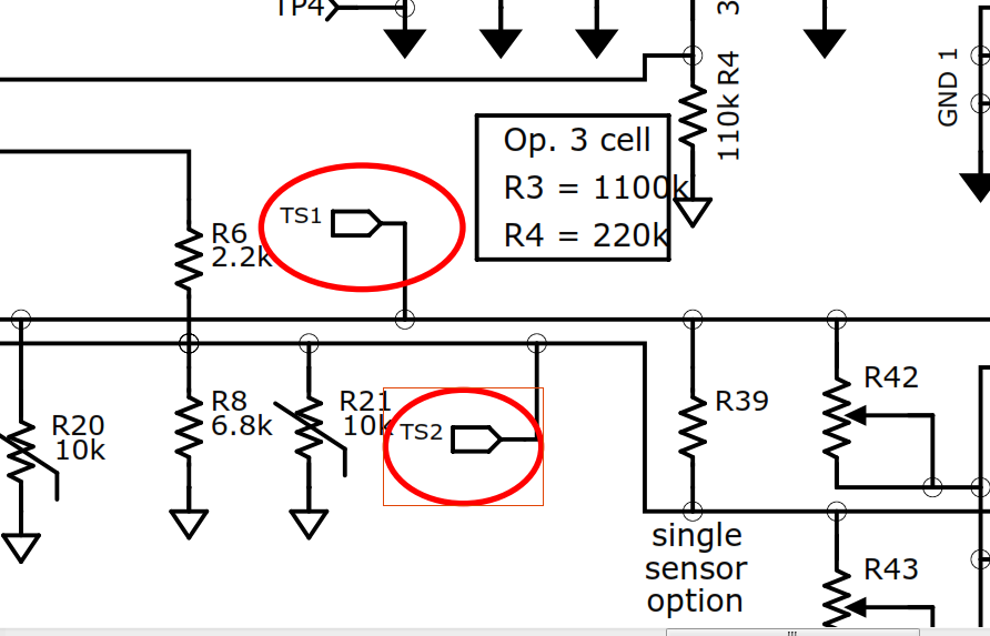
1) I know that while using li-ion battery one must monitor the temperature and according to that program the charging current and voltage in this IC there are two temp sensor input pins . in Evm user guide i found that two thermistors are being used are those  enough for the design .

2) there is an inward directed arrow like box tagged Ts1 what is it is it temp sensor input . i am not clear about that symbol.

3) please explain me this symbol . 

please help me with this .


  • Hi Noble,

    This symbol is essentially a port, used to reference a connection elsewhere in the schematic. The other connections for TS1 and TS2 are in Figure 5 of the EVM user's guide, showing the test pads available on the board.

    This EVM has extra connections for customer evaluation of the device. As you can see, R20 and R21 are the basic thermistors, while R42 and R43 are redundant potentiometers for experimentation. Additonally, external connections can be made at J16 and J17, and if only one temperature sensor is used, TS1 and TS2 can be tied together using R39. Section 8.2.1.2.6 of the datasheet mentions that these must be tied together if only one thermistor is utilized.