This thread has been locked.
If you have a related question, please click the "Ask a related question" button in the top right corner. The newly created question will be automatically linked to this question.
Hi,
We got a question from my customer about TPS2042B-Q1.
Could you help us?
[Question]
- When the device is exposed to absolute minimum voltage(-0.3V) of OUTx, what is the failure mode?
They found failed sample during evaluation. That is short between VOUT1 and /OC1. They were analyzed their board and they found that the cause of failure might be undershoot of OUT1.
So they want to know failure mode by exposed to absolute minimum voltage(-0.3V) of OUTx.
And they want to confirm their guess is right or not.
Best Regards,
tateo
Hi Tateo,
Thank you for considering TI devices, just wanted to emphasize on operating a TI device at the absolute ratings conditions, such operation may cause a permanent damage to the device as stated in the datasheet under "Absolute Max Ratings", but we can certainly look at your customer test circuit and test conditions and we maybe able to help with their failure analysis.
BR,
Haidar
Thank you for your replay.
My customer evaluated an over current condition by electronic load(CC Mode). When OCP condition cotinued, the device became hot and thermal shutdown is occured. And then Vout fell and reached to negative voltage -1V to 0.4V for 200msec. *This is under-shoot. They also evaluated by CR mode. The under-shoot was not occured. They found cause of undershoot. But they want to know cause of destruction. They think that the cause might be over heat or unders-shoot. So they want to know failure mode of under-shoot of OUT1. And they want to confirm the cause of destruction.
Best Regards,
tateo
I'm sorry for the long delay in my reply.
I got screenshot of thier test.
Could you check it?
Best Regards,
tateo
Hi Tateo,
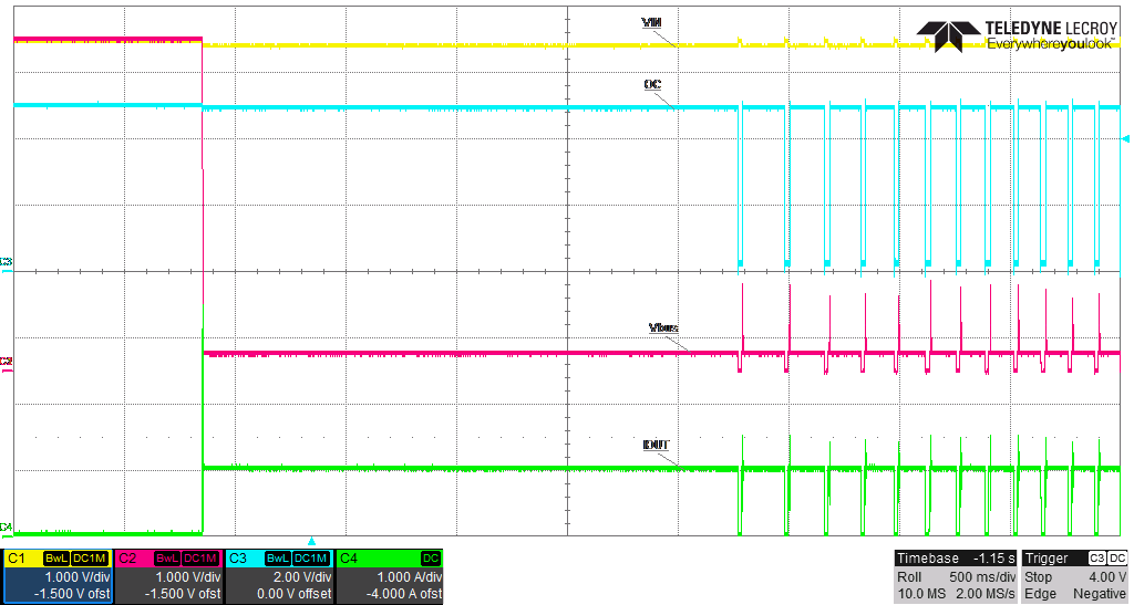
Sorry for the late reply but I wanted to replicate your customer’s test on a similar device and compare what I got with what your customer got, please see attached screenshot of the test.
In your customer test, I noticed a weird behavior of both OC and IOUT curves, so when OC condition occurs while the device is enabled (as in your customer case) and at the instant the overload occurs, high current may flow for a short period of time before the current-limit circuit can react, then the device switches into constant-current mode which I didn’t saw in their test also if the load was beyond the recommended operating current of the device, temperature of the device will rise until thermal limit of the device is exceeded then OC asserts and the device will enter thermal cycling which also it didn’t happen in their test!!!???
As you can see in test result I conducted, the device behave as it should under similar test condition (similar to your customer). So one possible explanation could be a flipped connection to electric load device, also you told me that they did the test using resistive load (without electric load) and didn’t got the undershot and I was wondering if they got a result like the one I got in my screenshot?
Best regards,
Haidar