This thread has been locked.

If you have a related question, please click the "Ask a related question" button in the top right corner. The newly created question will be automatically linked to this question.

Timing of PWM dimming for LP8860

I would like to confirm PWM and LED ON/OFF for LP8861.

I attached waveform for PWM, LED cathode and anode.

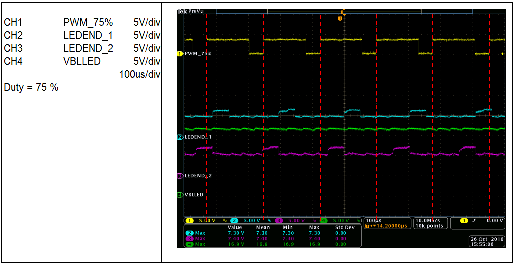
CH1 is PWM at LP8860 PWM pin.

CH2 & CH3 are LED cathode side signals and connected to two of LP8860 OUTx (x: 1~4).

CH4 is LED anode side signal and connected to LP8860 output.  

You can see the following in the waveform.

- CH2 & CH3 ON/OFF timing don’t match PWM ON/OFF timing

- CH2 ON/OFF timing doesn’t match CH3 ON/OFF timing  

Are those behaviors are expected or did they do something wrong? LP8860 works like this?

I think those timing should match each other.  (Ex. CH1 ON -> CH2 & CH3 OFF, CH1 OFF -> CH2 & CH3 ON)

Best regards,

Atsushi Yamauchi

  • Hi Yamauchi-san,

    Yes, this behavior is designed in this way which is called "Phase shift PWM"

    Each string is shifted by 90 degrees to make total 4 string = 360 degrees. This function will reduce load transient condition better, and resulted PWM output freq higher, so visual artifact can be improved. PWM input freq is not necessarily same with PWM output freq in this case. LP8860 is TI's advanced automotive LED driver, and has this feature, but LP8861/LP8862 don't have this(only direct PWM mode supported).

    Hope this helps,