This thread has been locked.

If you have a related question, please click the "Ask a related question" button in the top right corner. The newly created question will be automatically linked to this question.

Stability problems with LMZ22003

Other Parts Discussed in Thread: LMZ22003

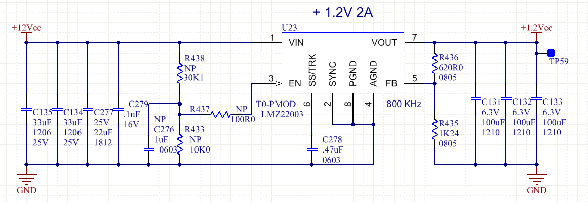
recently, we got stability problems with LMZ22003

The simulation was made with National Webench

Vin 11.5 to 12.5V
Vout : 1.2V
Iout 1.19A
Temp: 65degC

Every simulation was completed with success, and the design is in production since 2012.

Now, If I try to simulate with same parameters, the Ti-Webench indicate : Warning Phase margin 32.6deg < 35deg. This might lead to an unstable design!
The LMZ22003 seems to have become unsuitable for the same parameters.


Is it possible to get the LMZ22003 stable with the 1.2V out and 1A out?

Regards

  • Hi Alain,

    The design should be ok, i saw on the datasheet for the curve of efficiency at 1.2V up to 85 deg ambient (see Figure 31 on the datasheet). If you change the webench input to 3A, i can see that webench will generate the design for you. How much phase margin that you have on your previous design?

    Thanks
    -Arief
  • Hi, thanks for the fast response.
    The phase margin of the old simulation (2011) was 42.782deg

    Now, the phase margin using Ti-Webench with same parameters is < 35deg. Webench did not generate the design...
    Yes, if I try to simulate with 3A load, the phase margin is OK. But, in our application the max consumption is 1.19A, and the typical value is 600mA. With this load the phase margin is now < 35deg!

    The design using National LMZ22003 was perfectly validated on the products over temperature and >10K power cycle.
    We had >1000u in field without any issues since 2011.

    Now we begin to get some stability problems in production tests.
    Meanwhile, we are validation a new PCBa using the same design, and the switcher is really unstable under room temperature with 500ma to 1A load. 3/5 system tested had failed the first power-up. Replacing the switcher solve the problem.

    Does the simulation model had changed from National to TI?
    Does the die had some changes? Did you have any electrical PCN?
    The date code of the part presently tested is 39ATC8G3.

    Regards
  • Hi Alain,

    I will forward this info to our webench and product engineer. In the meantime, do you have the schematic/layout of your design?

    Just to clarify, the PCB is changed from the previous version to the newer one? 

    Thanks

    -Arief

  • HI Alain,

    I have manage to ask the Product Engineer and he told me that the die is the same there is no PCN for the part.
    As for the failure, i think the Schematic/BOM and the layout would be helpful to debug the issue

    Thanks
    -Arief
  • Hi Arief,

    Here is the last data from production,

    Qty fail vs qty tested
    Feb-2016  6 / 70
    Apr-2016   8 / 70
    May-2016  5 / 70
    Jully-2016  1 / 70
    Aug-2016   1 / 70
    Oct-2016    0 / 100

    On the new project/PCB, we had to replace 4 / 20 switcher. The PCB layout of the new project is the same as the old product.

    All capacitors are ceramic. The pin EN is unconnected.

    Does your engineer can confirm that the LMZ22003 is stable @ 12Vin, 1.2Vout, 1A lout ?

    The date code of the new LMZ22003 is 39ATC8G3

    Regards

  • Hi Alain,

    Do you have the original webench design? So that we can compare it to the current design.
    The reason that i ask is because i want to check if the output capacitor ESR changed because the ESR will affect the phase margin of the design.

    Also, when you say it is failing does it mean that it fails the first time you power on or you managed to power up the circuit then fails after a while.

    I look at the datasheet and it seems that there is a 2Mohm pull up to VIN on EN pin, but normally i would connect EN to some input (resistor divider or VIN) just to make sure noise does not couple in to this input.

    Thanks
    -Arief
  • Hi,

    One of the old simulation was made on 5/26/2011.
    https://webench.ti.com/webench5/power/webench5.cgi?lang_chosen=en_US&DesignId=224
    Now if I try too run the simulation : "Your simulation failed due to a netlist error"
    Cin: 300mOhms, 100uF
    Cout: 14mOhms, 330uF

    If I try another old simulation
    https://webench.ti.com/webench5/power/webench5.cgi?lang_chosen=en_US&DesignId=204
    "Warning: Phase Margin: 32.5 < 35deg"

    All problems found was at the 1st power-up. We found some LMZ22003 with output shorted. When we replace the part, the system goes good and we are not able to reproduce the problems.
    On some system tested, the voltage output was at 1.0V at the boot-up and goes at 1.3V after 10minutes. (configured for 1.2V)

    Did you have made some changes in the max reflow temperature? Our temperature profile is the same from 2011.

    Regards

  • Hi,

    Which temperature profile that you use for soldering the module part?
    We have this guideline for the temperature reflow of the part
    www.ti.com/.../snaa214b.pdf

    It seems that the document is updated on 1/19/2016, therefore you can try to match it with the one you currently use for the part

    Thanks
    -Arief