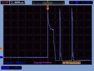
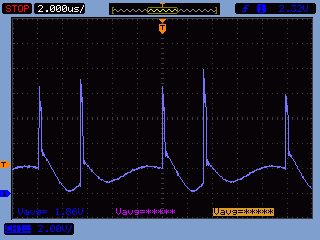
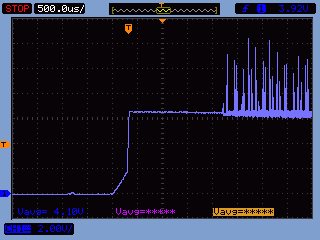
We are using a TPS40303 as a 12V to 5V@4A converter in a controller product that is under development. In a small number of cases (two so far in perhaps 30 PCBs made) the converter fails to start after a couple of weeks of reliable operation. I have attached a plot of the voltage at pin 2 (EN/SS) which appears to show the controller repeatedly trying to start up. The four high frequency spikes in each repeat are at about 1.3us period (770kHz). The cycle repeats about every 16.2 us (61.7kHz). I note that about 9 in 10 cycles look like the wider ones and about 1 in 10 are somewhat narrower.
We are using the converter in spread spectrum mode to reduce EMI issues.
From a quick diagnostic look it seems the controller is unable to drive the high side FET correctly, replacing the controller beings the system back into operation so indicates the issue is not directly with the FET.
We have a 3R3 resistor on the BOOT pin, and the FET gates are currently not current limited, and have 0R in series. I have seen mention that the BOOT pin resistor could be increased to slow the turn on of the FET, is this likely to be a useful change?
Currently I cannot post the schematic here directly as I do not have permission to show it in an open forum but it is roughly based on your data sheet and application notes. I am able post in private if needed.
Best regards
Marc.


