This thread has been locked.

If you have a related question, please click the "Ask a related question" button in the top right corner. The newly created question will be automatically linked to this question.

UCC2813 - start or stop the PWM controller in response to input voltage.

Other Parts Discussed in Thread: UCC2813-5, UCC2813-0

Hi all

Would you mind if we ask UCC2813-0 to UCC2813-5?

Our customer would like to start or stop the PWM controller in response to input voltage.
So, we consider that it is possible to make it using Reset IC as follows file.


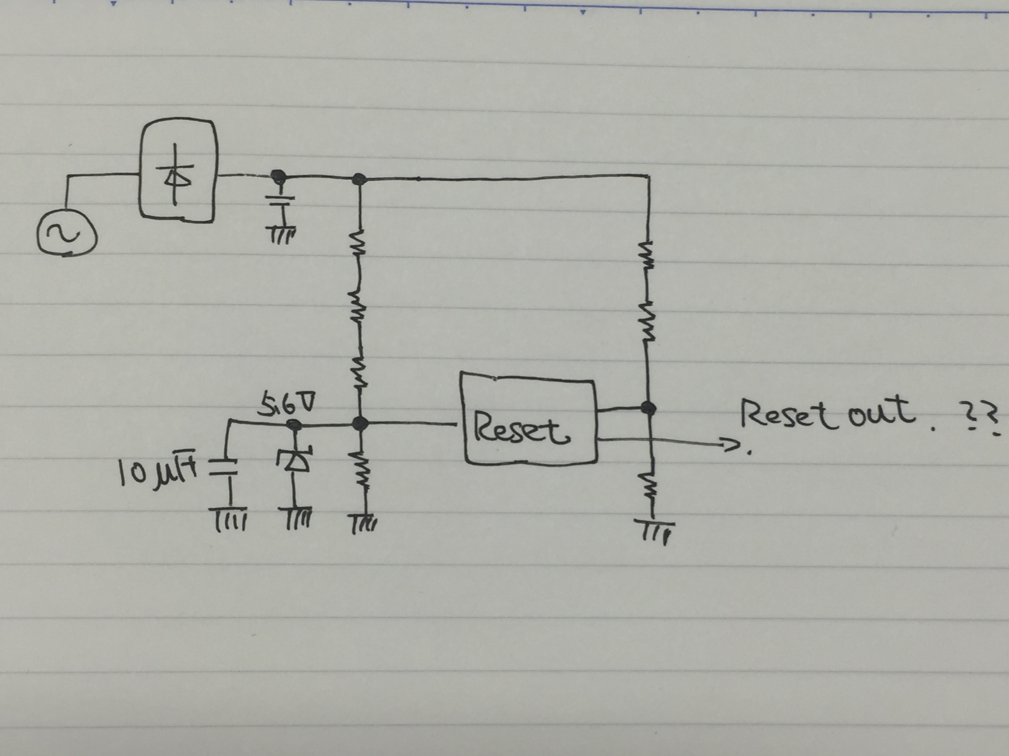
In this case, where should the reset device's output connect to PWM controller?
Could you let us know it, if you have some advice?

Kind regards,

Hirotaka Matsumoto

  • Hello Hirotaka,


    The UCC2813 error amplifier output is current limited to roughly 500 mA.  It is designed  so you can pull it low to demand 0% duty cycle with a FET.  I suggested you use this pin to stop PWM switching.


    Regards,


    Mike

  • Mike san

    Thank you for your reply!

    Does it mean that REF pin connects to low to stop PWM?

    And, you mentioned "The UCC2813 error amplifier output is current limited to roughly 500 mA".
    Recommended Operating Conditions of REF pin output current is 5mA
    500mA seems that it is too big. Is 500mA value correct?

    Kind regards

    Hirotaka Matsumoto

  • Hello Hirotaka,

    This will only stop PWM switching and will not turn off reference.

    The 500 mA should have been 500 uA.   Sorry about the mistake.

    Regards,

    Mike

  • Mike san

    Thank you for your support always!
    Ok, we use comp pin to stop PWM output.

    Kind regards,

    Hirotaka Matsumoto

  • Mike san

    We have some additional questions.

    When COMP is low, an internal capacitance for softstart t=4ms is not discharged, right?
    So, when COMP releases low condtion, the output operates without softstart.
    That's why, is it possible to add capacitance to COMP pin for softstart?

    Kind regards,

    Hirotaka Matsumoto

  • Hello Hirotaka,

    I was discussing this one of my colleagues and he pointed out that you could reactive soft start by activating the 1.5-V threshold on the current sense pin. This feature is covered in section 8.3.12 of the data sheet. 

    If you are using the level shift circuitry presented in figure 26 or have a resistor between the CS pin and CS resistor you could pull up on the CS pin to trip the 1.5V over current activating the soft start. You should be able to do this with a NPN transistor collector tied to Vref and the emitter tied to the CS pin.  The based would have a pull up resistor equivalent to the resistor between the CS pin and the current sense resistor and you would control the base of the transistor with a FET.  Please note these resistors should be large enough in size as not to dissipate too much power.

    The other option you have is to feed the UCC2813 with a series pass regulator using a NPN transistor setup a voltage divider. You could first the device into UVLO by pulling base of the NPN transistor low with a FET.  This will also initiate a soft start on the restart of the device.

    Regards,

    Mike

  • Mike san

    Thank you for your cooperation always!

    OK, we persuade that our customer consider to use the CS pin to trip the 1.5V over current activating the soft start.
    On the other hand, could let us know followings?

    <Question1>
    How much is the threthold of COMP pin for low?

    <Question2>
    Please refer to the follow file.
    20161216_UCC2813.pdf

    Kind regards,

    Hirotaka Matsumoto

  • Hello  Matsumoto,

    The resistor values are of equal value and the total impeadence is greater than 10K.

    The interntal reference to the none inverting amplifier to the comp pin is Ref/2.  However,  I believe you might be looking for how low the comp has to be pulled down to demand 0% duty cycle.  I would recommend pulling the comp pin below 600 mV to ensure the output demands 0% duty cycle.

    Regards,

    Mike

  • Mike san

    Thank you for your reply!

    The resistor values are of equal value and the total impeadence is greater than 10K.
    ->Ok, we got it, however could you let us know how much the value of each resistances are?

    Kind regards,

    Hirotaka Matsumoto

  • Mike san

    We are sorry to rsuh you, however could you let us know about last update?

    Kind regards,

    Hirotaka Matsumoto

  • Hello Hirotaka,

    Unfortunately the impedance of this resistor divider is not a tested a parameter and characteristic data is not available for the resistance of this resistor divder. This impedance can vary with process and temperature and the total impedance will be greater than 10 k.

    The resistor ratio of this divider will be maintained and the error amplifier feedback will be able to adjust for any variation in the internal load impedance.

    Regards,

    Mike
  • Mike san

    If it is possible, could you let us the approxy resistor ratio?

    Kind regards,

    Hirotaka Matsumoto

  • Hello Matsumoto-san,

    I'm sorry for the delay in our reply. Mike has been out of the office due to the holidays.
    In the UCC2813-x datasheet, page 17, Figure 25 shows the resistance ratio to be 0.65R to 1R, top to bottom.
    The actual values are not well controlled, but the ratio between them is quite tight. The top resistance is approximately ~65K and the bottom R is ~100K in value, but these values can deviate from nominal considerably (+/- 20 ~ 30%), due to silicon process variations.
    However, they both vary in the same direction by almost the same percentage so their ratio is always held close to 0.65 : 1.

    Regards,
    Ulrich