This thread has been locked.

If you have a related question, please click the "Ask a related question" button in the top right corner. The newly created question will be automatically linked to this question.

TPS53015: TPS53015 Schematic recommendations

Part Number: TPS53015

Hi Team,

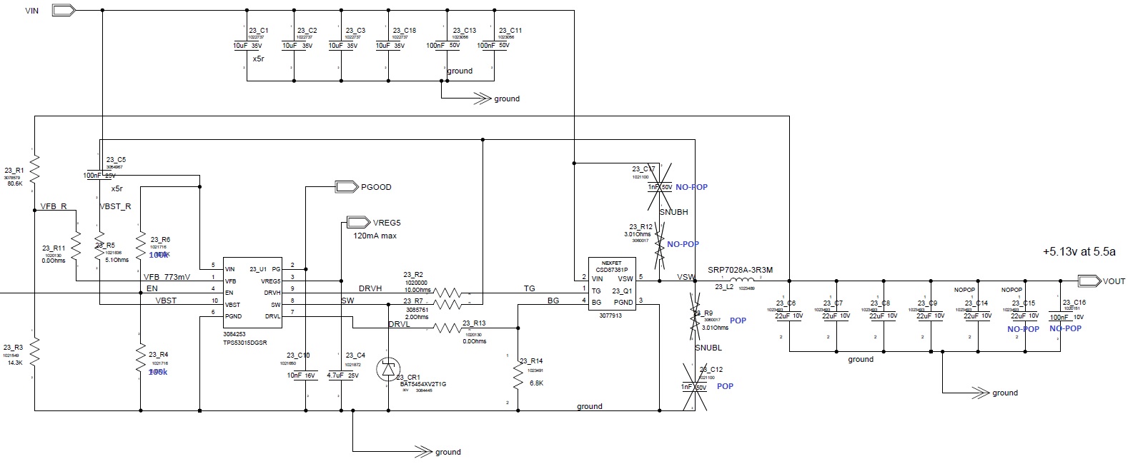
One of my customers is currently facing issues with our TPS53015. They are experiencing  lock out when they try to power on after an immediate power outage. These are their specs:

Vin = 24V Nominal, 15V at Sleep mode, can dip as low as 10.5V

Vout = 5V

Iout = 6A

When a power outage occurs, their AC/DC power supply that supplies the 24V Vin does not completely drop to zero. it would drop to around 4V and would slowly decay to zero after a few mins. This causes the TPS53015 to remain on because they are using a voltage divider circuit on their enable pin. I have attached their schematic below using two 100k resistors. 

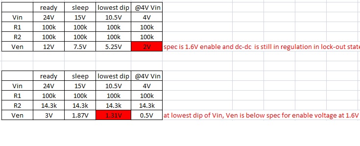
When the Vin dops to 4V, the voltage at the enable pin would be 2V which is above the VEN_H threshold of 1.6V. If they try to adjust the voltage divider so that the enable pin would drop down to the VEN_L threshold of 0.5V, the Ven would drop down to 1.31V and would be below the VEN_H Threshold. Below is a table of the values. 

I hope to get your feedback and do let me know if you have further questions.

Thanks! 

Best Regards,

Alfred

  • The most likely scenario is that you are triggering UVP protection, which is latching and requires a power cycle or EN toggle to recover.  If Vin drops to about 4.25 V, that should be enough to allow  UVP event to occur and latch the IC off.  You will need to carefully measure the VIN voltage where UVP occurs on a number of boards and ensure EN goes low before that point.

  • Hi John,

    Thanks for your response. I will send an email to discuss further on this since I want to share with you additional info that is under NDA.

    Thanks!

    Best Regards,

    Alfred

  • Hi Alfred,

    The resistor divder on EN pin prababoly does not work in this applicaiton.
    One possible solutin is to replace the high-side 100kohm resistor with a Zener diode, and update the bottom resistor value based on the current rating of zener diode.
    With this solution, after VIN drops below certain level, the zenor diode does not conduct current and EN voltage will be below OFF threshold.

    You can also use other signal to control EN on/off.


    Thanks
    Qian
  • Hi Qian,

    Thanks for your recommendation!

    I think the zener diode would work, but would this be an efficient solution?

    Thanks!

    Best Regards

    Alfred