Because of the Thanksgiving holiday in the U.S., TI E2E™ design support forum responses may be delayed from November 25 through December 2. Thank you for your patience.

This thread has been locked.

If you have a related question, please click the "Ask a related question" button in the top right corner. The newly created question will be automatically linked to this question.

BQ24071: BQ24071 with a BQ27510-G2

Part Number: BQ24071
Other Parts Discussed in Thread: BQ27510-G2,

Hi,

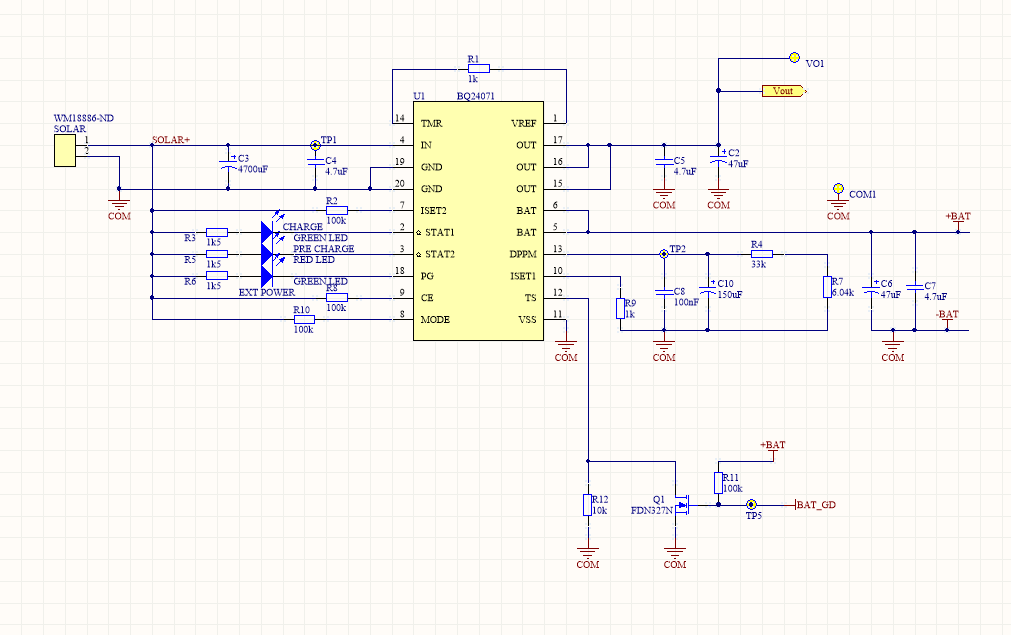
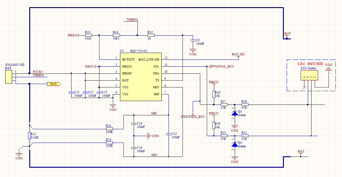
I have a device that charges a 3.7V Li-Ion battery using a BQ24071, with a BQ27510-G2 as fuel gauge. The device can/should be charged with either a 5V solar panel or an AC adapter. The diagrams used in the design are

Charger:

Fuel Gauge:

Note that the TS pin on the charged is connected to a pull up to the BAT_LOW/GD on the fuel gauge. That pin is configured to ouput BAT_GD in a low level, so, when the battery is not Ok the TS pin is shorted to ground.

Overall the charger works fine, but if for any reazon the battery gets completly discharged (to the point that the PCM kicks in), when the IN (solar panel/adapter) is restored, the battery wont start charging, unless its unplugged and plugged again.... and If the device is solar powered in the middle of nowhere, this is a time consuming problem.

What could be the problem?, is it fixeable using the current design?

Regards.

  • Hello

    Normally, when VBAT is 0.1V lower than regulation voltage, the IC will recharge. What's the battery voltage when over discharge? Could you make an independent experiment, use stable 5VIN, use an equipment(like electronic load, or source meter) connects with VBAT, firstly, VBAT 4V, then decrease VBAT to a very low value, view the charge current.

    Regards

  • Hi,

    I think you didn't understand the problem. The charging/discharging works fine when there's a source that charges the battery before it's completely discharged. My problem is that when the charging source is gone (or with a low current) for a few days, for example, a solar powered device in the winter, the battery will discharge to the point the internal PCM of the battery kicks in and cuts out the output because of the overdischarge protection. At this point, the VBAT is 0, and nothing much can be done about that, but, when the source is available once again (sunny day!) the device turns on but the battery won't start charging. When that happens, VBAT raises to 1.5-2V (why??, from the charger I guess). Note that the PCM has a discharge detection voltage of ~2.6V and a release voltage of ~3V, so the battery is still not working.

    My working theory is that since the internal regulator of the BQ27510-G2 is supplied by VBAT, and 2V isn't high enough to turn it on, the fuel gauge stays off. And, since the BAT_GD pin is an open drain collector, the pull up on the TS pin of the BQ24071 switches the NMOS Q1 shorting it to ground, disabling the charger because of the temp protection.

    Considering that, I've tried changing the supply of the BQ27510-G2 internal regulator to Vout (at the charger) instead of PACK+. I thought that since the fuel gauge would turn on when the source is restored, it would drive the open collector on and it would start charging. But then, the VBAT went up to 4V even when there was no battery connected (is that supposed to happen?), so the fuel gauge is on, but it detects a battery, so the charger is trying to charge all the time.

    So, my questions are, is there any other way to solve this issue?. Is using the TS pin connected BAT_GD the correct approach to communicate the charger whether it should start charging or not?.... or even further, is the combination of those both ICs OK for this application (gauged battery charger that can be charged with a solar panel or an adapter)?. I found an application note of a battery charger with a fuel gauge combined, but not the sames ICs.

    Regards,
    Luis