This thread has been locked.

If you have a related question, please click the "Ask a related question" button in the top right corner. The newly created question will be automatically linked to this question.

UCC28700EVM-068: Our new requirements

Part Number: UCC28700EVM-068
Other Parts Discussed in Thread: UCC28700, PMP10344, UCC28740, STRIKE, TPS2490

Hi Sir,

We used this UCC28700 in our main products, it works very well. But we have a new question that needs us to boost voltage from 12VDC to 24VDC. We hope to get your help.

Our requirements:

1. input voltage range: 110VAC-480VAC.   

2. Output voltage: 24VDC (our original output voltage is 12VDC),

3. Output capability:  24W or 25W 

4. Best output channel: 3 channels. Channel one: 24VDC/0.4Amp; Channel two: 24VDC/0.4Amp and third channel: 12VDC/0.4 Amp.  

If it is possible, we hope three output voltage channel are different, 24V/0.4A;24V/0.4A, 12V/0.4A    

Best regards   

 Jim Yin

  • Jim,
    Thanks for your interest in TI here.
    To be sure I understand, are you asking how to modify your design from what you have for 12v to 24v out?

    If so could you share what power level the 12v design was, a schematic of the 12 design , and transformer details of your 12v design?

    Regards
    John
  • PMP10344_REVC.pdf

    Hi John,
    Thank you very much. yes, You gave me a reference design for 12VDC output two years ago.
    Please review attached document. What difference both ours and your reference is one phase in our design while your design is three phase.

    In our new design, we hope keep 25W output power. but it should be like this: 24VDC/0.4A, 24VDC/0.4A and 12VDC/0.4A

    Thanks and best regards
    Jim Yin

  • Hi Jim,

    Just to clarify, do you need all output rails to be isolated like in PMP10344 design? or it is okay to stack the transformer winding to get different outputs?

    The reason why I ask you about this is because the multiple output PSR flyback tends to have slightly poor performance for regulation and transient performance, and it might exceed ±5% of load regulation depend on the transformer specs and design.

    You might need to consider using SSR flyback such as UCC28740 for better regulation and transient performance for your applications. Could you please let us know what is your target line and load regulation accuracy?

    Thanks

    Wei-Hao Chen

  • Hi Wei-Hao,

    Thank you very much for your response. There are two things I have to tell you.

    1. We have tested UCCUCC28700.

    2. I believe that PMP10344 and UCC28740 work very well, but we have to test first.

    I hope you can help us to supply associated schematic, PCB source file, demo board and your test result for your UCC28740.

    We finished all design and test work two years ago, but operator change and update requirements, so it would be very kind for

    you to support us for our new requirements.

    Our original requirements: Input voltage range: 110VAC-480VAC

                                               Output voltage: 12VDC

                                               Output power:25W---real power may be 16 to 17W

    But since we added a backup capacitor bank back up circuit that needs higher voltage to reduce capacitor size and value, we need 24VDC output

    New requirements:   input voltage range: 110VAC-480VAC

                                     output voltage range: 12VDC, 24VDC

                                     output power: 12VDC/3W, 24VDC/20W


  • Hi Jim,

    Thanks for your reply and let us know your requirements. 

    Please note that downsides of multiple outputs PSR flyback will be the load regulation and current limit are not going to be accurate when different loads are applied on different output rails due to it only senses the total peak current on the primary side. If the loads are extremely unbalanced, i.e. one rail with heavy load and the other with no load or lightly loaded, it will fail to clamp the output level on the lightly load rail and higher output voltage might be seen as the result.  As a consequence, additional measures may need to be taken to limit these voltages, if necessary.

    It will have to rely on your system (load) to balance the amount of current that should be drawn on each rail to achieve stable outputs. Since PMP10344 worked quite well for your application so I would suggest you to stick with UCC28700 and you can probably modify the transformer winding ratios and to achieve your desired outputs for  +24V and +12V.

    Here are some suggestions you could try: 

    1. Since output voltage for two rails are doubling of the original +12V design, you can simply double the secondary winding turns for those two output rails. Please to make sure you resize the secondary diodes and capacitors rating for the +24V output. 

    2. One temporary test could be done using your existing system is to remove all the components of one +12V output rail, and take the open winding in series with the other +12V winding to double the turn ratio for +24V output. Again please keep in mind the diodes and capacitors have to be replace with higher ratings for +24 output. The original windings were good for 0.7A average output for each rail, so the new series winding should be able to support 0.7A average output as well.

    You can test the revised system to verify the performance such as ripple, regulation, spike voltage, thermal and etc. until you get the new transformer available.

    One more thing, did you use your own transformer for your current system or you use the exact one in the PMP10344? We can probably help you to find the datasheet and spec. for the X'FMR that used in PMP10344, so you can use it as a reference for your new transformer design.

    Thanks a lot.

    Best Regards,

    Wei-Hao Chen

  • Hi Wei-Hao,
    Thank you very much for your help. Yes, your design supports 0.7Amp output current. Can I connect all three output coil in series to get 36VDC/0.7Amp for this UCC28700 circuit? If there are some potential problems for connection in series ?
    Thank again and best regards
    Jim Yin
  • 36VDC.pdf

    Hi Wei-Hao,

    Thank you very much for your help. Please review attached schematic and check if our design has some potential problems.

    We use this PMP10344 to generate 36V/0.7A output.

    Thanks again and best regards

    Jim Yin

  • Hi Jim,

    I do not see any major issue with it, but maybe it would cost more to stack-up three rails to achieve higher outputs than putting three windings in series. The number of components on secondary side will be tripled, and the size of the board will be larger as well.

    Other than that, just to make you have select the correct rating of diodes and capacitors on the secondary side and it should be fine.

    Please do no hesitate to reach us if you have any further question.

    Thanks for supporting TI!


    Best Regards,

    Wei-Hao
  • Hi Wei-Hao,
    Thanks very much. Yes, we can connect three secondary coil in series to generate 36VDC. I understand that we have to use higher voltage diode and capacitor. I have another question for the resistor, original 12VDC output is 10kom, how can I select this resistor at 36VDC output? same?
    again, 22uF/25V--------> 22uF/63V or higher ?
    1000uF/16V----->1000uF/50V or higher?

    Thanks again and best regards
    Jim Yin

  • Hi Jim,

    You can keep the dummy load of 10K for 36VDC, the purpose of the dummy load is to maintain the output regulation and prevent the output voltages from drifting high under light load condition.

    And 22uF/63V & 1000uF/50V cap sounds pretty good for +36V output, it has at least 30% margin for the derating.

    Thanks.

    Best Regards,
    Wei-Hao
  • Hi Wei-Hao,
    Thanks very much. It is great.

    Best Regards
    Jim
  • Hi Jim,

    Not a problem at all, please do not hesitate to tell us if there is anything you would like to know.

    And thank you very much for your continuing support TI's product.

    Best Regards,

    Wei-Hao

  • Hi Wei-Hao,

    One more question, the reverse voltage of SK4200L-TP (output rectifier diode) is 200VDC, can we continue to use this chip at 36VDC output environment?

    Thanks again and best regards

    Jim Yin


  • Hi Jim,

    It would need higher rating rectifier diode for that. The negative reflected voltage will increase as the overall turn ratio increases. Based on the transformer turn ratio in PMP10344 design you might need the reverse voltage rating with 600VDC diode to be safe.
  • Hi Wei-Hao,
    I built a prototype to test the circuit. Its output voltage is good (36VDC),but its current is very low, only 0.22Amp. It is only 8W, 1/3 of designed power output. I hope to know how to adjust output current. I am afraid that we have to use three separated rectifier circuits.
    Please help me for this issue.

    Thanks again and best regards
    Jim Yin
  • Updated_36VDC.pdf

    Hi Wei-Hao,

    Please help me to review attached schematic and try to find any faults.

    Best regards

    Jim Yin

  • Hi Jim,

    Could you please let us know what happen when you increase the load to 0.22A or higher? does the output voltage drop and the controller kept in CC mode?

    Thanks!

  • Hi Wei-Hao,
    Thanks very much. Yes, it kept in CC mode.
    Load Current
    66 Ohm 529mA
    84 Ohm 416mA
    101 Ohm 343mA
    119 Ohm 292 mA
    136 Ohm 255 mA
    160 Ohm 218mA

    The output voltage dropped and seems oscillation.

    When load is 160 Ohm, the output voltage is stable and kept at 35.6VDC

    Thanks again and best regards
    Jim Yin

  • Hi Wei-Hao,
    Today, I adjusted resistor divider value according to the equation you supplied.  I keep RS1 no change (82k Ohm) and I changed RS2 from 22 KOhm to  25.7 Kohm (Voct=36V). But the result is the same.

     Rs1= (Vin(run) *1.414)/(Npa* Ivsl(run))

     NPA = 14/3;

    VIN(run) =70

    IVSL(run) = 260uA

    Rs2 = (Rs1 * Vvsr)/(Nas *(Vocv+Vf)- Vvsr)

     VOCV = 36V

    VF= 0.55V 

    NAS = 3/6

    VVSR=4.05

    Hope to get your help soon.


    Thanks
    Jim

  • Hi Wei-Hao,
    I adjusted VS input resistor divider value according to the equation you supplied. I keep RS1 no change and adjusted RS2 as 25.7 kohm (36VDC output, Nas =3/6, Nas: transformer auxiliary to secondary turns ratio). But the result is the same.

    Thanks and hope to get your help soon.

    Best regards

    Jim
  • Hi Jim,

    Thanks for your reply and sorry for the delayed response, we had pretty bad snowstorm strike yesterday.

    I think your VS resistors values are fine because your can get 36V at 200mA, but it loses regulation when load gets heavier. And the controller is still in CV mode from the results of different load condition you had tested. 


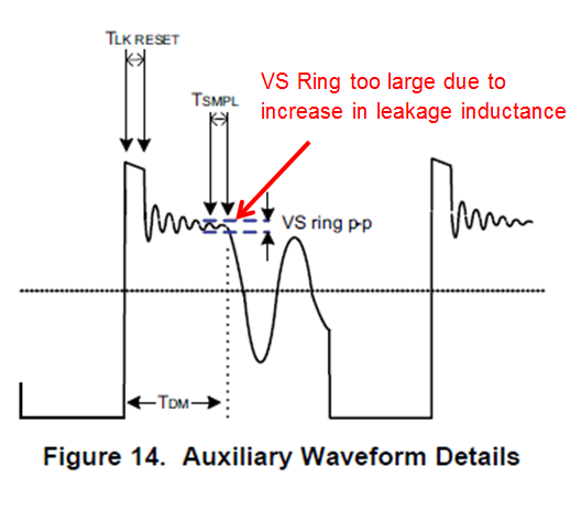
    The problem could be the leakage inductance of the transformer became larger as the three windings are now in series, this resulted in larger ringing on reflected auxiliary voltage, and the controller sampled incorrect timing of VS voltage due the ringing and failed to regulate the output at your desire level. The tolerable ripple on VS is scaled up to the auxiliary winding voltage by RS1 and RS2, and is equal to 100 mV x (RS1 + RS2) / RS2.


    Could you help us to get a waveform of the auxiliary winding voltage and output waveform when the load is around 200mA and 500mA?

    Also please refer to the transformer datasheet as link provided below:

    /cfs-file/__key/communityserver-discussions-components-files/196/6622.750817930r00.pdf


    Thanks!

  • Thanks very much Wei-Hao. I will send you waveform soon.

    Best Regards
    Jim Yin
  • Hi Wei-Hao,
    Thanks very much.
    As we discussed that the power supply worked correctly in light load. But we found that After it started up, I added heavy load (60 Ohm load---0.6Amp), power supply can work correctly too.

    It means that in heavy load situation, power startup is not correct (may be difficult to oscillate). After power on, it has not any problem to work in heavy load.

    I will send you waveform tomorrow morning.

    Best regards
    Jim Yin
  • Hi Jim,

    Have you captured the waveform for the aux winding yet?

    Thanks
  • Hi Wei-Hao,

    Thanks very much. I am sorry that these days I was busy for other issues.

    There are two questions for our power supply:

    1. Same as we discussed before----36VDC output/0.7Amp (three coils connected in series),

    2. Highly capacitive load problem. It always work abnormally even 12VDC output (thee 12VDC/0.7Amp output connected in series after rectifier). So we have to consider using a in-rush current limiter or a load switch for start up. (we use a backup capacitor bank as a load of this DC/DC converter )

    Best regards

    Jim Yin

  • Hi Jim,

    Thanks for the reply and no worries please take your time.

    1.  It would help if we can see some waveforms of the auxiliary winding and maybe change the snubber type to RC snubber will help to reduce the ringing due to increase in leakage inductance.

    2. Indeed, you are right about it. You are expected to see the large inrush current due to high dv/dt of the capacitive load during start-up. TI has a series in-rush current limiter known as hotswap controller (External FET) or E-fuse (Integated FET).

    I would recommend TPS2490 hotswap for your application, it offers start-up inrush current limiting, over current protection, short-circuit protection, and undervoltage protection and please refer to the links below:

    TPS2490:

    Product Folder: http://www.ti.com/product/TPS2490

    Datasheet: http://www.ti.com/lit/gpn/tps2490

    Also the evaluation board might be helpful for you to understand how it works:

    TPS2490-EVM:

    Product Folder: http://www.ti.com/tool/tps2490evm-001

    User Guide: http://www.ti.com/lit/pdf/slvu099

    Thanks.

    Best Regards,

    Wei-Hao