This thread has been locked.

If you have a related question, please click the "Ask a related question" button in the top right corner. The newly created question will be automatically linked to this question.

Supercap charge circuit using TI load switch

Other Parts Discussed in Thread: TPS22929D, TPS22918, TPS22953, TPS2115A-Q1, TPS2115A

Hi

I have an 5V application with a 0.47 (1ohm ESR) supercapacitor which is used as backup supply when the external supply is disconnected.

During power on, I would like to reduce the inrush charge current to max ~500mA. I have considered several solutions and have now stumbled upon the TI load switches which seems to be a possible solution.

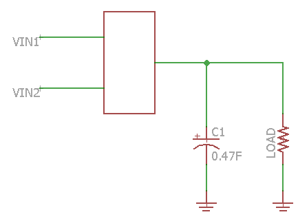
The circuit looks something like this:

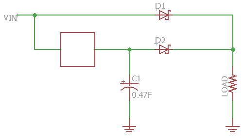
The empty box represents the load switch. When the external supply disconnects, VIN goes to zero and the cap (C1) supplies the load, allowing for secure shutdown. During boot and normal operation, the load can be supplied directly from Vin (not needed to wait for C1 to fully charge).

One of the main concerns is that C1 should not discharge back through the load switch towards the input when the external supply is disconnected. Also, as I do already have a voltage drop across D2, I need the drop over the load switch to be small.

The load switch should support the following:

  • Adjustable charge time up to several seconds (in order to stay below 500mA)
  • Reverse current protection (such that C1 does not discharge back through the load switch)
  • > 500mA continuous current
  • 5V in
  • Low drop down
  • Low price
  • Good availability

I have been looking at the following parts

TPS22929D

  • Good availability
  • Low price
  • Reverse current protection
  • NO adjustable rise time

TPS22918

  • Good availability
  • Low price
  • Adjustable rise time
  • NO reverse current protection

TPS22953

  • Not as good availability
  • Higher priced (over spec'en in regards to current)
  • Reverse current protection
  • Adjustable rise time

The TPS22953 seems to be the only single output part supporting both reverse current protection and adjustable output - can this be true?

Question:

Would you recommend using the TI load switches for such an application as this one (Please note that the required rise time in this application is much longer than the examples given in the datasheets)?

If so, which part would you recommend giving the requirements above.

I appreciate any help you can provide.

Thanks

Christian

  • Hi Christian,

    First of all, thank you for the detailed post, it makes it very clear what you are looking for.

    As far as load switches go, you are correct, the TPS22953 is the only device that features both reverse current blocking and an adjustable rise time. This device can be configured to have a long rise time in the seconds range, but thermal shutdown may prevent a smooth rise time. The best way to know how the device will react is by ordering an EVM and connecting the supercap you intend to charge.

    We have additional options with our eFuse portfolio. In this post here, one user decided to go with the TPS25942 eFuse device.

    Let me know if you have any questions.

    Thanks,

    Alek Kaknevicius

  • Hi Alek

    Thanks for your reply.

    I will definitely order some parts and test it out.

    Looking further into your power IC's I found that the power multiplexers might be able to do the same and at the same time render the diodes in above schematic unnecessary.

    A range of the power multiplexers support current limiting and reverse protection. E.g. part TPS2115A-Q1 can be set to a specific current limit.

    I have browsed datasheets and the forum, but have not been able to find a clear answer to what happens if the current limit is reached. In order to charge the super cap, I need the current to be kept at the limiting value (e.g 400mA) until the cap has charged.

    The schematic would simply look something like this.

    Question: Do you know if the current will be kept at the limit (at least until the thermal safety kicks in) or if the device will shut down immediately?

    Thanks for your help. Much appreciated.

    Br 

    Christian

  • Hi Christian,

    Good question. There's another post here that helps answer this question. From the post:

    "This is a current limit foldback IC. The output voltage will foldback to maintain the current. Since the output folds back, there will be some dissipation on the pass FET. As such, the IC may reach thermal shutdown if the overcurrent is prolonged."

    Also, the TPS2115A comes in a non-automotive version if you don't need the automotive (Q1) qualification.

    Thanks,

    Alek Kaknevicius

  • Hi Alek

    Thanks for the reply.

    I will give it a try.