This thread has been locked.

If you have a related question, please click the "Ask a related question" button in the top right corner. The newly created question will be automatically linked to this question.

PMP10350: CORE DEVICE IS UCC28710D ON THE REFERENCE DESIGN

Part Number: PMP10350

Hello,

I have replicated the PMP10350 design as our Universal input 12 Volt supply.  In testing , I have noticed a problem.  I have a 45 Watt (resistive)  load on the 12 Volt output as I run our board thru temperature.  Approximately, between -35 degree C and -36 degree C there is a power up issue.  If you leave the board to bake at or below those temperatures with power off and then apply (about 120 Vrms or at any other AC voltage) - the 12 Volts does not come back up.  However, if you leave the AC power and 45 Watt load on during the bake and toggle the AC off (for about 5 seconds) and then back on - the 12 Volts return.  During the cold boot problem the attached Volt meter (attached to 12 V output) shows a brief pulse about every 4 - 5 seconds, but is never able to recover.  Any suggestions on how to proceed?  At those temperatures in our environmental chamber its a little difficult to troubleshoot.  By the way I have tested two boards and both are consistent.  Also there is no other problems all the way up to 85 degree C.  

Thanks for any advice

  • Jeff,

    Does the startup issue only happen at certain load (i.e. full load) and/or certain line voltage (i.e. low line only)?

    Can you get it to start at no-load, or lighter loads, or higher line voltage?


    To help debug the issue, is it possible to observe some waveforms? I know this is difficult at cold temp in the thermal chamber, but it will help to figure out the cause of the issue. In particular, it would be good to see VDD, DRV, Vout and the AUX winding. Looking at them on a slow time scale should show VDD charging and discharging as the IC hiccups due to some fault. Then zoom in and trigger on DRV at about 10-20 us/div should show the first 3 PWM pulses which are used to assess the system, after which the IC may give up if a fault is detected.

    This step by step debug guide could be useful for you:
    www.ti.com/.../slua783.pdf

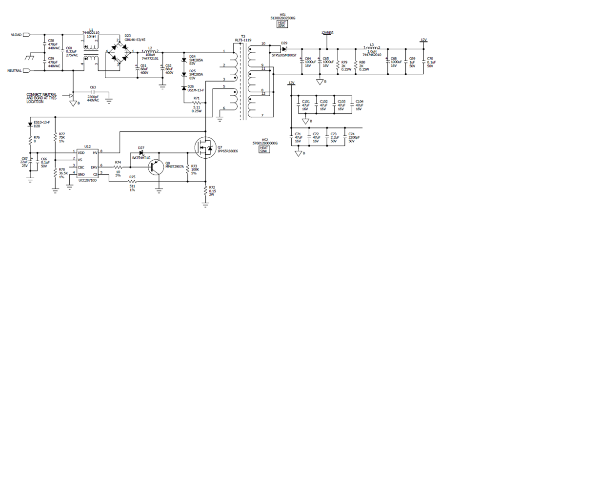
    Also, can you post your schematic with values and transformer details (inductance, turns ratio, core size, number of turns etc?

    Thanks,
    Bernard
  • Hi Bernard,

    Thanks for your response.  This is a fixed resistive 45 Watt load.  Adjusting the line voltage doesn't change the result - does not appear to be line voltage dependent.  Furthermore, without the 45 Watt load the cold boot problem goes away, so it's definitely load and temperature dependent.   I will read the pdf and monitor the signal as suggested.  Also, the IC does not appear to "give up", it continues to pulse without much success.  I did notice once around the hiccup temperature (-35C to -36C) the 12 V output did come up; however, very slowly.  It looked like with each attempt (pulse)  the voltage increased by 1 V - 2 V per attempt until it reached 12 V.  Below is the circuit.  Thanks for any future input.

     1 V - 2 V per pulse and eventually made it to 12 V.

  • Jeff,

    Can you test with a variable output load to see at what load level the issue occurs? Also monitor VDD and Vout. I would expect that the output will come up at lighter loading, and that there is an upper limit where this issue starts to occur - and the limit likely drops lower at lower temperatures.

    I suspect that the electrolytic caps are not behaving well at low temperature, and most likely the VDD rail is struggling to keep the controller running long enough for Vout to get to a high enough level for VDD to be powered from the AUX winding, and then VDD is going into UV shutdown.

    The VDD cap C67 (22 uF 25 V Rubycon part, if you used the same part as the PMP10350 BOM) has a poor impedance ratio at -40 C compared to +20 C - the ratio is 6:1 according to the Rubycon ML series datasheet - which means that the internal cap esr increases a lot when cold (the C value also probably drops, both contributing to an impedance increase). This causes a lot more VDD ripple, making it far more likely to run into VDD UV issues.

    The impedance ratio at -20 C to + 20 C is less severe, 3:1. The ratio is probably so bad this type of cap because its a very small can size, larger caps would have a better ratio - the output caps for example at 3:1 impedance ratio between -40 C and +20 C, and they are much larger.


    I would recommend using a larger cap size (physical can size) for C67, and/or a larger cap value. Or switch to ceramic caps, or a mix of large-value ceramic plus electrolytic to try to get better performance at cold temps.

    Hopefully this will help solve your problem.

    Note that the esr of the output and input electrolytics will also both increase significantly at cold temp, so bulk cap ripple and output pk-pk ripple will also get worse.


    One last point, I am curious about the connection of Y-cap C63 in your schematic - why is the end that connects to output GND (BGND) also bonded to Neutral? This effectively connects the output GND to AC mains, bypassing the isolation, and presenting a safety hazard if the output GND is accessible or user-touchable.


    Thanks,
    Bernard
  • From the customer:

    Hi Benard,

    Sorry for such a long delay - our Processor Board had arrived and I had to focus on it.  My Senior Tech was put on this issue with some input from myself; however, with no success.  The time has come to rectify the cold boot problem. 

    Since our last communication:

    • Removed C63 from schematic.
    • Added more capacitance to VDD - Did not affect the problem.  It took longer to cycle on/off (due to the capacitance).
    • No external load (other than 12Vout  capacitors and a very minimal 12V on board load)- still has temperature issue. 
    • Even removed D28 and used an external VDC supply (set to about 23V)  applied to VDD - still had problem.  Thinking that perhaps transformer was not up to spec and if we supplied a nice clean supply on VDD the 12Vout would take off - but it didn't.
    • Eventually, applied external 12VDC to the output - thinking if 12Vout was already at 12V - maybe the 12Vout would stay up when external source was removed - it did not.

    From experimentation - it does not appear anything I do to VDD or Vout changes the outcome.  Did TI ever test the design cold booted at -40 C?  Going back to the BOM only D24 and D25 are different (from my memory) from TI's BOM - same value but not exact part number.  Other than D24/D25 and the board layout - its a cut and paste design from the recommended.  I know your board is not for sale; however, are there any third party manufacturers using same/similar design we can purchase?  Any information/advice/assistance is welcome.

    Thanks

  • Viktorija,

    We need to see some waveforms from the customer board to see what's happening.

    We need to see:
    VDD
    DRV
    CS
    Vout

    We need to see them on a slow time scale (~1 s/div), and zoomed in to the first several switching cycle (~10 us/div).

    Is the supply only giving a single or a set of 3 switching pulses when VDD reaches the 21-V start threshold? If so, then a fault of some kind is being detected, and the IC is giving up and going through a VDD discharge/charge cycle and repeatedly attempting restart.

    Is the supply delivering switching pulses, with Vout ramping some of the way towards 12 V but never getting there? This could be because the VDD level is falling to the UV threshold before the transformer aux winding can supply VDD. Which could be due to too small VDD cap (although they say they tried a bigger value and it didn't help). It could also be that the output cap is too large, or the CC-mode output current limit is too low to supply the load plus charge the output caps. Or it could be that the TVS clamp (D24 D25) is clamping too low and looking like a voltage-dependent short, allowing Vout to charge only so far and then causing it to plateau too low.


    If we can see some waveforms, it will help us to decide which if any of these might be the cause.


    I will check with the original designer of PMP10350, but generally most of the these reference designs are only evaluated at room temp.

    Thanks,
    Bernard
  • Hi Bernard,


    I will do my best to get the information requested. Some response to comments:


    1.  It could also be that the output cap is too large, or the CC-mode output current limit is too low to supply the load plus charge the output caps:

    I biased 12 Vout with 12V from external supply – Output capacitance negated when already at Voltage.


    1.   Or it could be that the TVS clamp (D24 D25) is clamping too low and looking like a voltage-dependent short.

    I also tried placing P6KE6V8C9 between D24 and D25 to boost the voltage – did not change results.


    Thanks