This thread has been locked.

If you have a related question, please click the "Ask a related question" button in the top right corner. The newly created question will be automatically linked to this question.

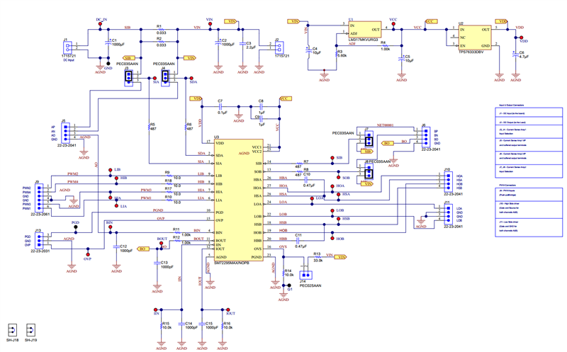
SM72295EVM: Strange Outputs - MSP430 driven inputs

Part Number: SM72295EVM
Other Parts Discussed in Thread: SM72295, , LM317

Howdy,

Currently helping on a design that is using the MSP430 to drive the inputs of the SM72295 with two PWMs that are opposite of each other. One PWM is tied to HIA and LIB, and the other is tied to HIB and LIA. By doing this we expected the HOA and LOB to turn on their FETs, then HOB and LIA to turn on theirs next cycle.

When we look at the outputs the low side FET gate signals are correct. One is high while the other is low and they alternate back and forth, but the high side outputs are constantly held high.

Any idea what could be wrong?

Regards,

Kevin

  • Hi Kevin,

    I have asked one our applications engineers to respond to your post, you should see a response soon.

    Regards

    Peter
  • We may have figured it out. Found in the EVM User's Guide where it mentioned you need 4 independent PWMs so we rewrote the code to do 4 PWMs instead of 2, but we haven't gotten word back if that worked.

    Thanks,
    Kevin
  • Hi Kevin,

    Did using separate MSP430 outputs resolve the behavior you had observed? I am glad to help further debug if you are still are experiencing issues. In that case, I would like to understand how the control pins are interfaced to the driver IC input pins (any resistors, caps, etc., vs. just tying pins together) and see the input and output waveforms as well as HSA and HSB.

    Regards,

    - Daniel
  • Unfortunately using separate PWMs didn't solve the issue.

    The PWM outputs of the MSP430 Launchpad are tied directly to the PWM inputs of the SM72295EVM. I'm attaching a few screenshots as you asked. I'm not seeing how to add pictures as attachments instead of placing them directly in the post so my apologies on that.

    Input signals

    LIB (CH1) and LOB (CH4)

    HIB (CH1) and HOB (CH4)

    Oddly enough when I looked at HSA and HSB their waveforms look exactly the same as HOA and HOB. When I turned everything off and checked the impedance between them there was about 10 ohms between HOA and HSA and 100 ohms between HOB and HSB. I'm not sure how they could be shorted together but that's kind of what it seems like.

    Final picture is of how the header pins are set up on the EVM. Might be a little hard to see but J3 and J4 have P1&2 shorted, J7 and J8 have P2&3 shorted. J14 is open.

  • Thanks for providing this information. From the attached oscilloscope screenshots, it seems VCCB (and I assume VCCA as well), is low. There is an under-voltage lockout feature for the high-side drivers that will disable the outputs unless the respective HB is above the VHBR threshold (typical 6.9V).

    Also, please confirm whether the circuit has FETs installed at the outputs. Without a low-side FET that pulls HS down to GND periodically, the HB supply will not be charged. This in turn means the high-side driver stage will not function.

    I have one other general recommendation (unrelated to the issue you are observing): I noticed in the screenshot that there is no dead time between the HIB falling edge and LIB rising edge and vice versa. A dead time is recommended to prevent a shoot-through condition at the output half-bridge.

    I hope this post helps. Please let me know what you find out.

    - Daniel
  • I noticed VCC was a little bit low (measured around 8.25V) compared to what the Users Guide says it should be (10V). But the feedback resistors on the EVM for the LM317 are set so it outputs 8.25V.

    There are no FETs installed on the outputs, thanks for letting me know that is a problem. I thought it would just give output signals with no FETs. This is probably our problem.

    As far as dead time, we've let the customer know it would be good to have dead time but he has assured us he doesn't need it.