This thread has been locked.

If you have a related question, please click the "Ask a related question" button in the top right corner. The newly created question will be automatically linked to this question.

LM25011-Q1: My design is pushing voltagebackwards

Part Number: LM25011-Q1
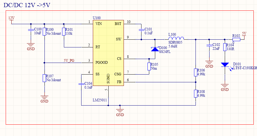
Other Parts Discussed in Thread: LM25011

Hello,

I have some issues with my prototype board.

Iam using LM25011 reference design more or less, 2A load @5V. 

I supply the circuit with 12V from and ideal power supply. But I measure 13V and the small ripple. On the output I get 1.5V with a small load. And when I measure the SW node I see its not swithing. 

Have I missed something? Just ordered a EVAL board with more or less the same design to compare. 

But does anyone have any good reason of the behavior? 

I can provide with pictures of the result of that is interesting. 

Thanks in advance. 

  • Hello,

    Regarding your schematic...looks OK, except you will need a pull up resistor for PGOOD pin to known voltage <7V. Suggested value for pull up resistor is 10K.

    Please re-test the circuit after this change. If still not operating, please check all the connections on test board (measure Vin on pin 1, check voltage on SW in, voltage on FB pin).

    Regards

    Brani

  • Hello Brani,

    Thank you for your reply. 

    I have been testing with the LM25011 eval board and the PG pin is floating there but still working properly. 

    The PG pin is not required for the function. 

    I have checked all connections. 

    Voltage:

    Supplied: 12V

    Vin: 12.4V (It is strange, should be lower because I also have serial diode filter function with Vf=0,3V)

    Vfb: 1.26V

    and the SW node is not switching and also 1.26V. 

    I have 3 boards and all shows more or less same behaviour. 

    Any other ideas?

    Thanks

    Leith

  • I found the problem!

    CSG pin should be grounded and connected to the sense resistor.