This thread has been locked.

If you have a related question, please click the "Ask a related question" button in the top right corner. The newly created question will be automatically linked to this question.

TPS54320: About Slow Start (SS/TR) tss

Part Number: TPS54320
Other Parts Discussed in Thread: TPS54040A, TPS54160

Hi,

Let me talk about the slow start spec of TPS54320.
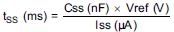
Datasheet has the following description.
Could you tell me the meaning of ”10% to 90%’’ marked with yellow.


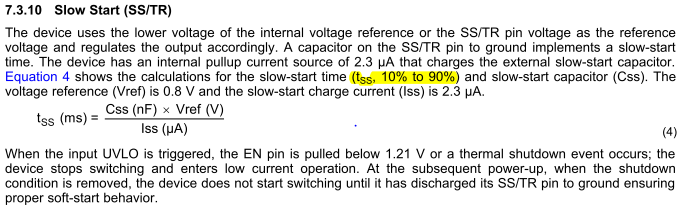
Currently, customers are comparing calculated values with actual waveforms.
Which of A and B should be compared with calculated values?


Could you give me your advice?

Best Regards,
Yusuke/Japan Disty

  • Yes the yellow marking is generally what I would use. The initial 10 % case is easy to define. The 90% final value is a little more difficult as the TPS54320 has a "soft hand over" between SS and VREF at the end of the SS time. So instead af an abrupt and well defined ramp, you get the gentle curve as shown in your waveform between the end of "B" and the end of "A". The intent of this feature is to eliminate the possibility of any overshoot on Vout for fast SS times.
  • Jone-san,

    Thank you for your kind support.
    Let me ask you one more thing.
    Do the following calculations consider "soft hand over"?


    Customer wants to match the measured value with the calculation result.
    However,
    The calculation result is 3.06ms ~ 3.88ms.
    The measured value B was 2.8 ms.
    (Css=0.01uF,Vin=5V,Vout=1.8V)
    I would like to know how to match calculated results with measured values.

    Could you be more specific about "soft hand over"?


    Best Regards,
    Yusuke/Japan Disty

  • The equation is just a derivation of the simple linear charge rate i = C * dV/dt.  For TPS54320, the FB voltage will track the SS/TR voltage within about 40 mV for most of the ramp, but diverges as SS/TR approaches 800 mV.  See the included graph:

  • Jhon-san,

    Thank you for your kind support.
    Your graph data (fig23) is not listed on the TPS 54320 data sheet.
    Where is this data from?

    Best Regards,
    Yusuke/Japan Disty

  • It is from a related device with the same SS characteristic. I do not recall exactly which one.
  • John-san,

    Thank you for your response.
    However, we can not contact the customer with a graph whose source is unknown.
    Do you have a Figure 23. SS/TR to VSENSE Offset vs Vsense graph of TPS54320?

    Best Regards,
    Yusuke/Japan Disty

  • Jhon-san,

    Thank you for your support.
    However, we can not contact customers with unknown sources.
    Your graph was data from the data sheet of TPS54040A.
    Can I consider the same characteristics as TPS54320?

    Do you have SS/TR to VSENSE Offset vs VSENSE graph data on TPS54320?

    Best Regards,
    Yusuke/Japan Disty

  • Not that i know of. I can search to see what datasheet it came from. May take a while though. Alternately I could take the data for TPS54320. That will take even longer. I would have to order an EVM, so it would be next week at the earliest. I can tel you that all the parts in that series behave the same way with respect to SS/TR. The file image i posted earlier was likely from a TPS54160 family device. TPS54160 has that figure as figure 24.
  • John-san,

    Thank you for kind support.
    If possible,I want you to obtain graph data of TPS54320.
    Is it possible to support?

    Best Regards,
    Yusuke/Japan Disty

  • Yes. Probably next week at the earliest.
  • Hi,

    Can I get the information?
    Customers need that information for design.
    If you need more information or if  I should  clarify my comment ,
    please let me know.

    Best Regards,
    Yusuke/Japan Disty

  • I have been back logged with other urgent projects. It is on my to do list. But I think you should convince your customer that the result wwill be the same as above. all these devices use the same circuitry for SS/TR function.
  • Hi,

    Let me ask you one more thing.
    When comparing Tss calculated value and measured value,
    Always more of the actual measurement value is slow.
    Is this correct in your understanding?

    The customer wants to fill up the gap between the calculated value and the measured value.
    Can you explain the details?

    TPS54320 waveform.pdf

    Best Regards,
    Yusuke/Japan Disty

  • The SS time equation uses a linear approximation of the SS rise time.  It does not take into account the soft handover near the VREF transition.

  • Also, just for your information, I have not yet received the EVM to measure the SS tracking offset voltage. It is on my pending list as soon as I receive it.
  • The EVM arrived it is not functional. I will look into this again next week, probably not until Friday as I will be OOO until then.
  • I have the data for TPS54320:

  • John-san,

    Thanks for sending me the data.
    I will submit the received data to the customer.

    Best Regards,
    Yusuke/Japan Disty

  • John-san,

    Thank you for your support.
    I understood about .
    Let me ask you one more thing.

    You gave me the following advice.
    "The SS time equation uses a linear approximation of the SS rise time.  It does not take into account the soft handover near the VREF transition."

    However,There are cases where measured rise time value faster calculated rise time value.
    This fact is contrary to your explanation.
    I attach the document.Will you check it?

    8420.TPS54320 waveform.pdf

    Best Regards,
    Yusuke/Japan Disty

  • The datasheet equation assumes that the rise time is measured from 0% to 100% and is completely linear. So your measured rise time 10% to 90% will always be faster.
  • John-san,

    Thank you for your reply.

    However,The following contents are described in the data sheet.
    --------
    The device uses the lower voltage of the internal voltage reference or the SS/TR pin voltage as the reference voltage and regulates the output accordingly.
    A capacitor on the SS/TR pin to ground implements a slow-start time.
    The device has an internal pullup current source of 2.3 μA that charges the external slow-start capacitor.
    Equation 4 shows the calculations for the slow-start time (t SS , 10% to 90%) and slow-start capacitor (Css).
    The voltage reference (Vref) is 0.8 V and the slow-start charge current (Iss) is 2.3 μA.
    --------

    According to your explanation, customers need to measure from 0% to 100%.
    Customer needs to specify the rise time of the power supply to the application.
    For that reason,Customer wants to know the consistency between the measured value and the calculated value.
    Could you tell me about "measurement method of correct measurement value" and "how to fill in the divergence between calculated value and measured value".

    Best Regards,
    Yusuke/Japan Disty

  • The datasheet may say 10% to 90%. However the equation is tss = Css * Vref /Iss. That is the standard form of I = C dV/dt. Since the dV term is Vref, that means that it is ramping from 0 V to Vref or 0% to 100%. In any case it is an approximation because of the soft handover.
  • Hi,

    Thank you for dealing with this matter.
    May I make one last question?

    Could you tell me the reason why the data sheet specifies 10% to 90%.
    According to your explanation below,I think that actual measurement should be done between 0% and 100%.

    "However the equation is tss = Css * Vref /Iss. That is the standard form of I = C dV/dt. Since the dV term is Vref,
     that means that it is ramping from 0 V to Vref or 0% to 100%."

    Even if there is soft hand over function,The rise time should be longer than 0%~100%.


    Best Regards,
    Yusuke/Japan Disty

  • Based on the equation, I suppose 0 to 100% would be more correct.  But in any case it is still just an approximation as the equation does not account for the offset or soft handover.  Also, the tolerance of the current and capacitor are more than the difference between 0% to 100% and 10% to 90%.

  • John-san,

    I am grateful for your prompt response.
    I understand what you say.
    However,Customers have doubts that data sheets are written as 10% to 90%.
    Therefore, it is necessary to explain why the data sheet are referred to as 10% to 90%.
    Would you give us some more details?

    I am sorry to make you explain over and over again.

    Best Regards,
    Yusuke/Japan Disty

  • I did not author that text, so it is not possible for me to say exactly what the writer had in mind. I can say with total certainty that the equation describes 0% to 100% linear approximation. It does not take into account any variance or the soft handover. I can also suppose that 10% to 90% may be used because that is a standard definition of "rise time". Like I said, it is all an approximation.