This thread has been locked.

If you have a related question, please click the "Ask a related question" button in the top right corner. The newly created question will be automatically linked to this question.

LM3409: Abnormal LED Current Waveform In Low Duty Cycle Dimming

Part Number: LM3409
Other Parts Discussed in Thread: LM3414

Hi teams

Background: My customer using 2 pics LM3409 on one board to drive two different colors LED, the LED number in series is not the same. 

Setting: External FET parallel dimming, dimming frequency is 25Khz

Vin1=38V Vout1=22V  Vin2=48V Vout2=27V  two LED circuit using the same inductance value.  No output cap

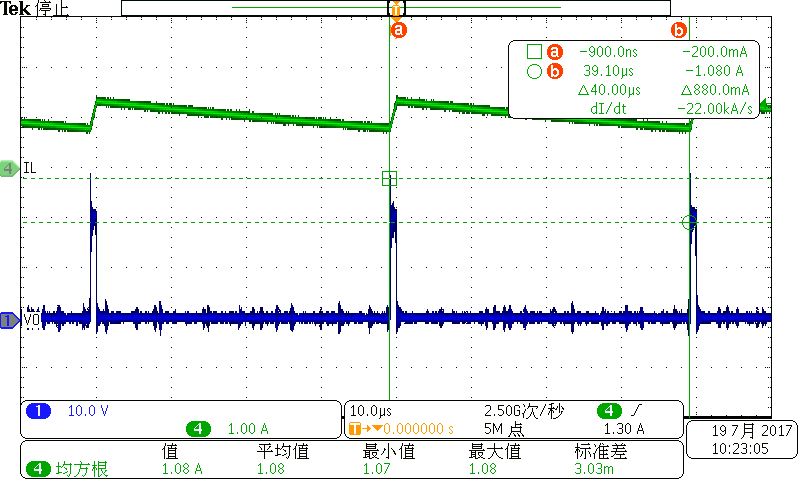
Issue: In low brightness dimming( dimming PWM duty cycle is very low) the LED current ramp up start point is different.

This issue won't happen when the duty cycle is higher.

Low duty cycle, the ramp up point is not the same

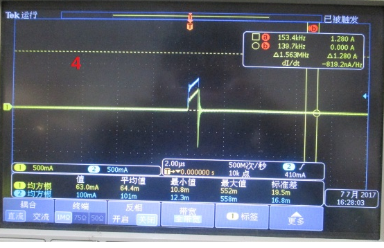
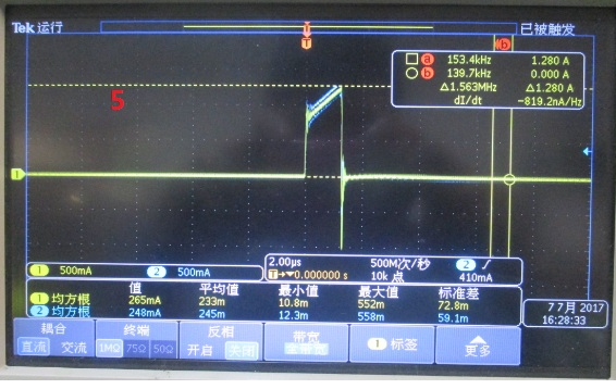
High duty cycle: The ramp up point is the same

  • Hello Gabriel,

    I'm actually surprised they match at any point. The only way the starting current each cycle, especially when the pulse width is less than a switching cycle, is to have the exact same duty cycle, switching frequency (during shunt FET on and off), and peak-to-peak inductor current ripple (during shunt FET on and off). You would have to ensure the inductor current is exactly the same for each every time the shunt FET turns off. The duty cycle for each is pretty close, but not exact, and I expect the switching frequencies are different.

    So you could tweak both to get all of those closer, but you will still never always get the same starting point at very low duty cycles most likely.

    Regards,

    Clint

  • Hi Clinton
    Thanks for you reply. There are couple more question:
    1) The same duty cycle you talking about is external dimming FET PWM duty cycle right? We can found that in figure1 the duty cycle is the same.
    2) Why the dimming duty cycle become higher the starting point will become the same?
    3) Do you have any suggestion for sloving this phenomenon? This phenomenon making the customer LED in different brightness in low dimming duty cycle.
  • Hello Gabriel,

    I was actually referring to the converter duty cycle. I'm not sure exactly why it is the same at higher duty cycles, it may have something to do with the LED dynamic resistance as to why the variation. It may be possible to tweak it some.

    Is there any way you could share a schematic? I could take a look and give you some things to try. Let me know.

    Thanks,

    Clint

  • Hi Clinton

    Today I talk to the customer's face to face and have several points to update:

    1) When they using parallel dimming they also disable the converter through EN pin when the external FET short the LED to the ground.

    2) When the  dimming duty cycle is not extremely small the inductor waveform is like this:

    The inductor current will keep discharge when the external FET short LED to ground (the converter was disable at this time)

  • Hello Gabriel,

    The two should have a similar discharge profile since that is due to the FET Rds(on) generate voltage (v=Ldi/dt). But with the same equation you can see the charge profile (di/dt) will be slightly different since v is different between the two. So when each are able to turn on and reach the peak current set by CSP-CSN they will behave similarly.

    But when you get so low that the peak is never reached you can have them reaching a different peak value during the on time and the result will be a different value during the off time when you turn back on. I'm not sure this can be avoided unless you can make the Vin-Vout the same for each so that you have the same di/dt during the on time.

    Regards,

    Clint

  • Thank you for your comments. I thing making the VIN1-VOUT1=VIN2-VOUT2 is a proper solution for my customer.
    By the way, can i parallel a resistor (5K) between SW and GND to force the inductor current decrease to zero faster ?
  • Hello Gabriel,

    I'm not sure putting a resistor from SW to ground would help since the diode is forward biased when the inductor current isn't zero during the off time. But as I mentioned if you put some resistance in series with the shunt FET it will increase Vout when the shunt FET is on and that will make the inductor current decrease faster.

    Regards,

    Clint

  • Hi Clint
    Thank you for your suggestion,i have replyed the customer with this solution.
    One more question, my customer also using LM3414 and they try to use it to drive two LED string in parallel.
    They wondering to know will the current unbalance become very significant after the LED been using for a while and aged?
    Do you have some suggestion to prevent current unbalancing in parallel configuration?
  • Hello Gabriel,

    Parallel strings are pretty common and have been used for years. So I tend to think they should be fine, particularly the higher the string voltage the better the matching. I believe they all age in the same way so it's often not an issue.

    However, some people still worry about it. But really the only thing you can do without extra circuitry (or two drivers) that can help is to put some resistance in series with each string. It burns extra power but if one string voltage starts getting significantly less than the other the extra voltage can be dropped across the resistor to improve current balancing.

    Regards,

    Clint

  • Hi Clinton

    That's very clear thanks.