This thread has been locked.

If you have a related question, please click the "Ask a related question" button in the top right corner. The newly created question will be automatically linked to this question.

LM26480: LM26480-Q1: Buck outputs got sine wave superimposed on the output volatges

Part Number: LM26480

Hi

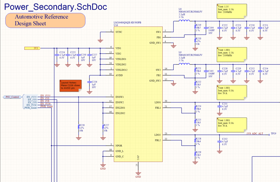
I am using the LM26480-Q1 to create 1.35V and 1.8V outputs via the buck converters. The input voltage is 3.3V and is stable.  Currently the LDO outputs are not used.

The schematic is attached below:

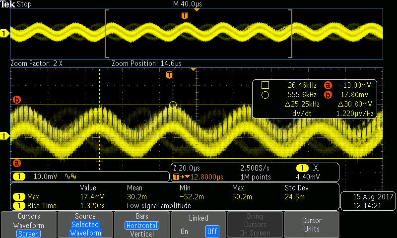
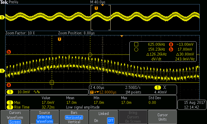
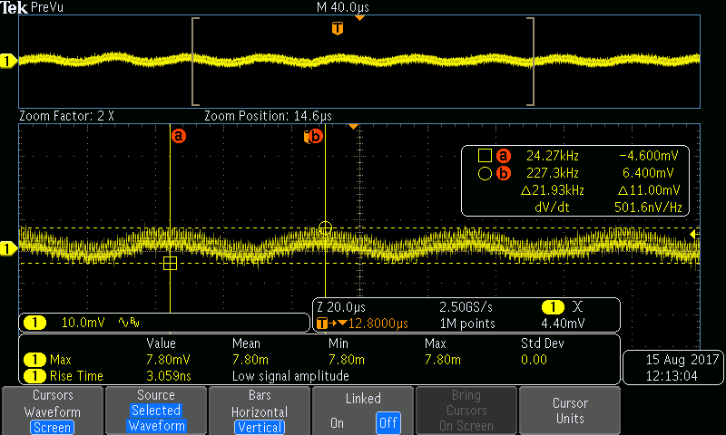
The issue is that both buck outputs has a sine wave on the output voltages. The sine wave on the 1.35V output is 31mV with a frequency of 24.5kHz as shown below. The 1.8V output has a similar sine wave but the amplitude is lower. The current drawn on the 1.35V output is 0.7A

The sine wave on the 1.8V is ok because it is a small percentage of the voltage, but I would like to get the sine wave on the 1.35V output smaller.

Any suggestions?

Thanks

  • Hi,

    This thread has been assigned to an engineer with expertise in this device. They will get back to you shortly.

    Thanks,
    Nastasha
  • Which version of the part are you using? QSQ-AA, QSQ-CF, or QSQ-8D? Both the QSQ-CF and QSQ-8D have Forced-PWM mode enabled, but the QSQ-AA does not.

    If the frequency of the "super-imposed" sine wave is different depending on the loading condition and disappears at full load, then you are seeing the effects of PFM mode and they are being smoothed out by the output capacitors to look like a sine wave.

    As you can see in Figure 20, the voltage ripple is higher in PFM mode than in PWM mode. If you put a full load on the output and the 25-kHz sine wave is replaced by a less-smooth switching waveform at 2-2.1MHz, then that proves PFM mode is the cause of what you are seeing.

    If this is the case, I suggest getting some samples of QSQ-CF or QSQ-8D silicon to see if the issue is resolved.

  • The device part number is LM26480QSQX-8D/NOPB. This device should run in forces PWM mode.

    Did some voltage captures of the 1.35V rail with different loads. Capture below shows the board idling with no additional loads.

    Capture below shows the board with 10Ω resistor load added to the 1.35V rail.

    Capture below shows the board with 1Ω resistor load added to the 1.35V rail.

  • Thanks for attaching the scope shots.

    Unfortunately, if the sine wave on top of the output voltage is the same across loads (~25 kHz), then it is not coming from PFM.

    There is no 25-kHz clock in the LM26480 and even if there were it would not produce such a smooth waveform.

    The only conclusion that I can draw is that the 25-kHz wave is being coupled onto the output voltages from somewhere else (hence, this is a conducted EMI issue).

    If the interference is off-board, then moving your testing setup may help resolve the issue. If the interference is on-board, it may be difficult to isolate the source of the interfering waveform. Do any other ICs on the PCB use a 25-kHz clock (or a multiple of 25-kHz that gets divided down, such as 50, 100, or 200-kHz)?