This thread has been locked.

If you have a related question, please click the "Ask a related question" button in the top right corner. The newly created question will be automatically linked to this question.

TPS65090: TPS65090 - Battery Backup Mode - Input Capacitance

Part Number: TPS65090
Other Parts Discussed in Thread: TPS54560

I have an issue with the TPS65090

From the datasheet:

In case the maximum adapter output current is not high enough to supply the complete system, the system can
be powered through the adapter and the battery at the same time. If the adapter current is limited, the adapter
voltage will drop to the battery voltage level and the backgate diode of the battery switch will conduct current.


To minimize the losses in this mode of operation, the battery switch is turned on. To detect whether there is still a
power source connected at the AC input, the AC power path switches are turned off every 0.5 s for a few
milliseconds. While the AC power path switches are off, VAC is discharged through a 1-kΩ resistor to GND. If the
voltage at VACS did not drop below the input UVLO threshold voltage, the AC power path switches are turned on
again to allow the power source connected to the AC input to supply the system again.

The problem is, this only works as intended when the AC input is completely disconnected, and the charger IC sees no capacitance.
If there is any capacitance on the input, even if there is no voltage/power coming in from the input, the system will backpower this capacitance, and the voltage at VACS will not drop fast enough in this 10 millisecond window, so the Charger IC will think there is a valid AC power source connected. Then, this input will fall after the capacitance is discharged (when AC switch is closed), and the cycle will continue forever.

We have an audio amplifier on our VSYS rail, so we hear noise every 0.5seconds when in battery backup mode, due to this.

Is there any way around this? It seems the charger can't handle any capacitance on the input. We have a buck regulator powering our input to the charger which needs output capacitance.
Ideally the Charger IC would wait longer for the input rail to fall to the UVLO voltage, instead of just 10 milliseconds.

  • Hi Manmeet,

    I've assigned your post to the expert and you can expect a response after the weekend.
  • Manmeet,
    I am looking into your question. Would it be possible for you to share your schematic. It doesn't have to be the full schematic, but the pieces around the PMIC, SYS out, VBAT and VAC in, would be very helpful.
  • VAC_IN

    VSYS/VBATT

    DC_IN_12V rail from first image (note we this has been changed to 13.6V now):

    *NOTE: I have also tested this with the EVM, with the same result (capacitance from a DC bench supply output causes the issue, disconnecting the connection completely from the bench supply removes the capacitance, and the issue disappears)

  • Manmeet,
    Got it, thank you. The schematics look ok at first glance. I will talk to the chip designers and see what feedback they have. I will get back to you asap, as soon I have more information.
  • Manmeet,
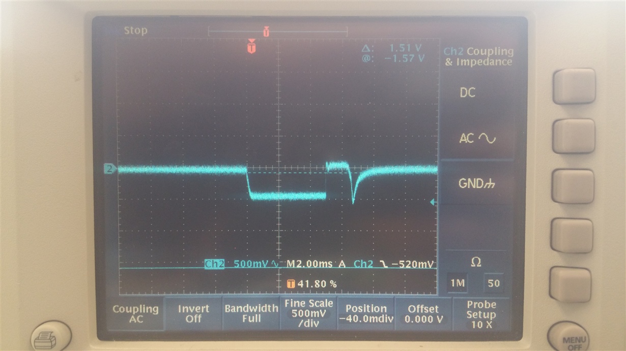
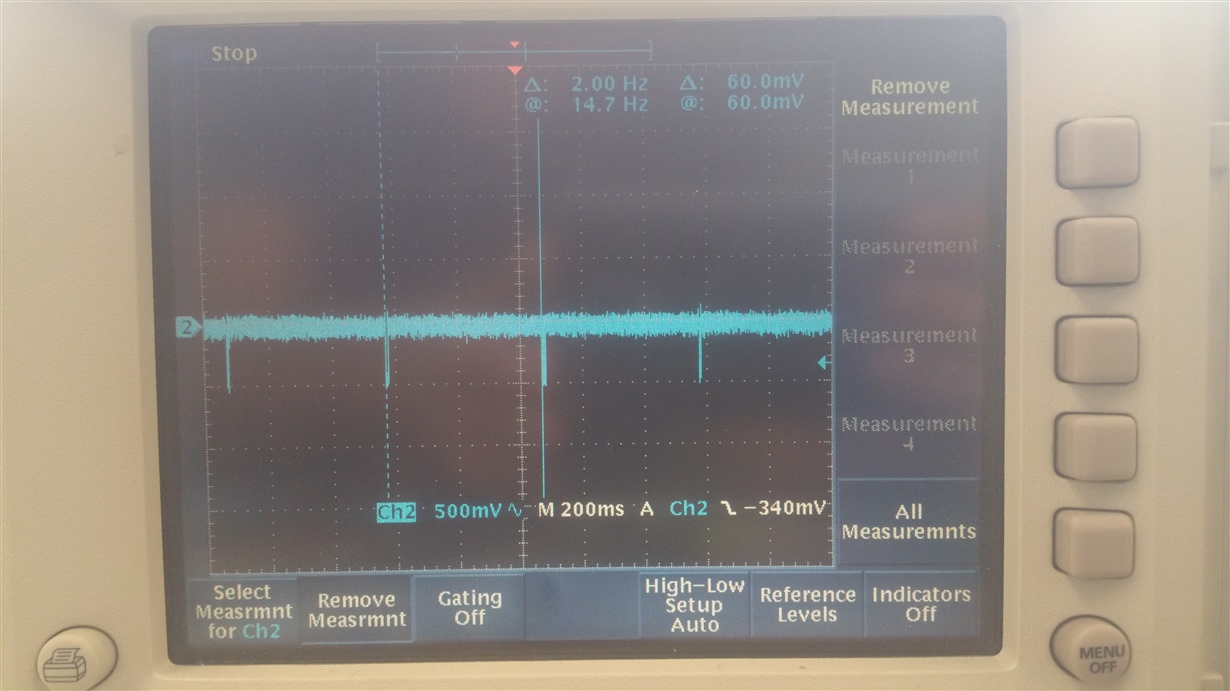
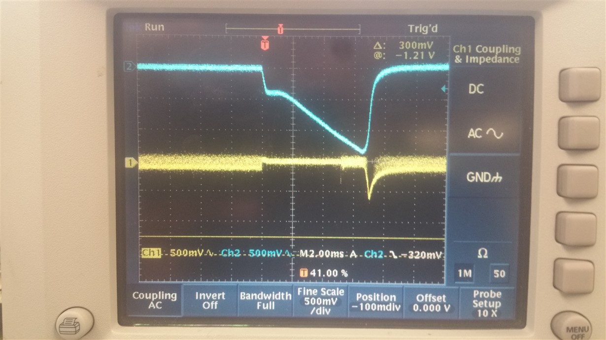
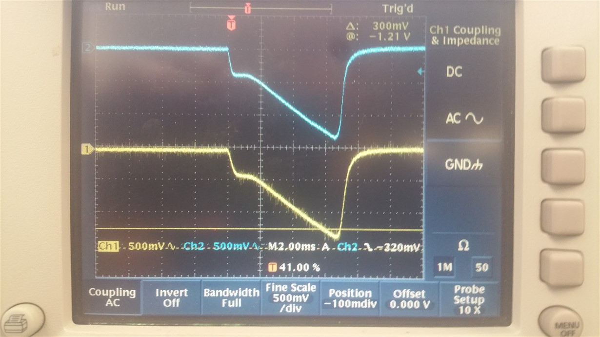
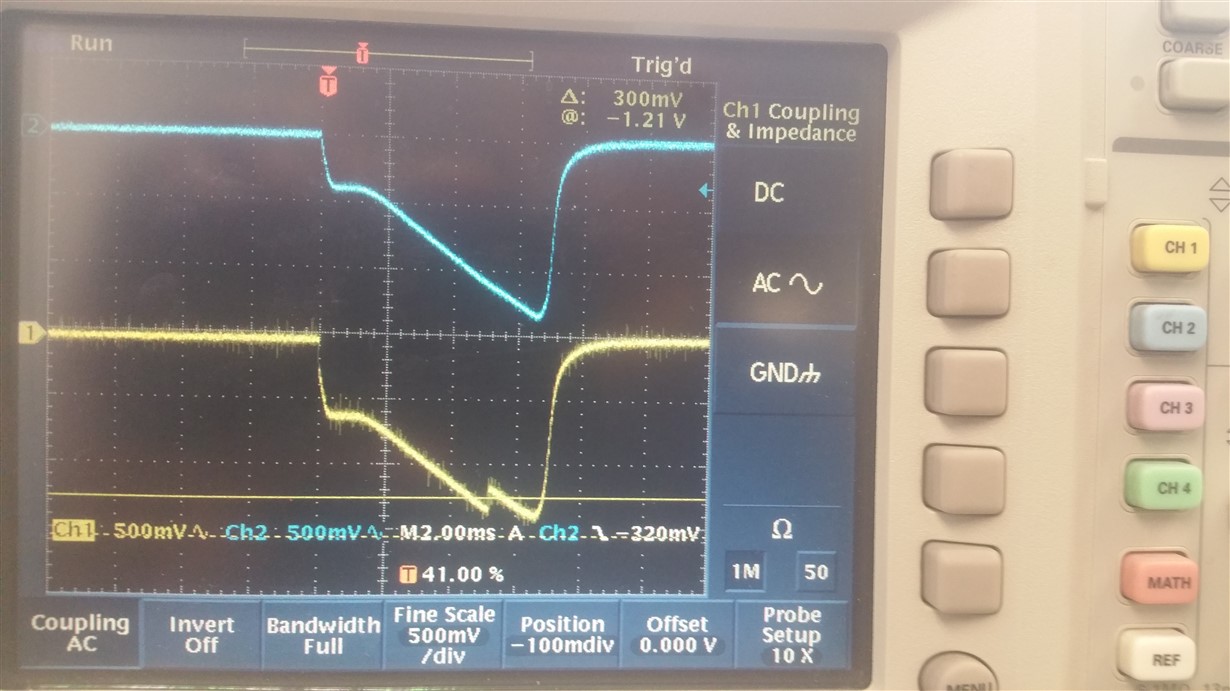
    Can you take a snap shot of the transient noise on SYS during the 0.5 Second sample.
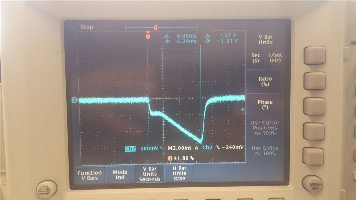
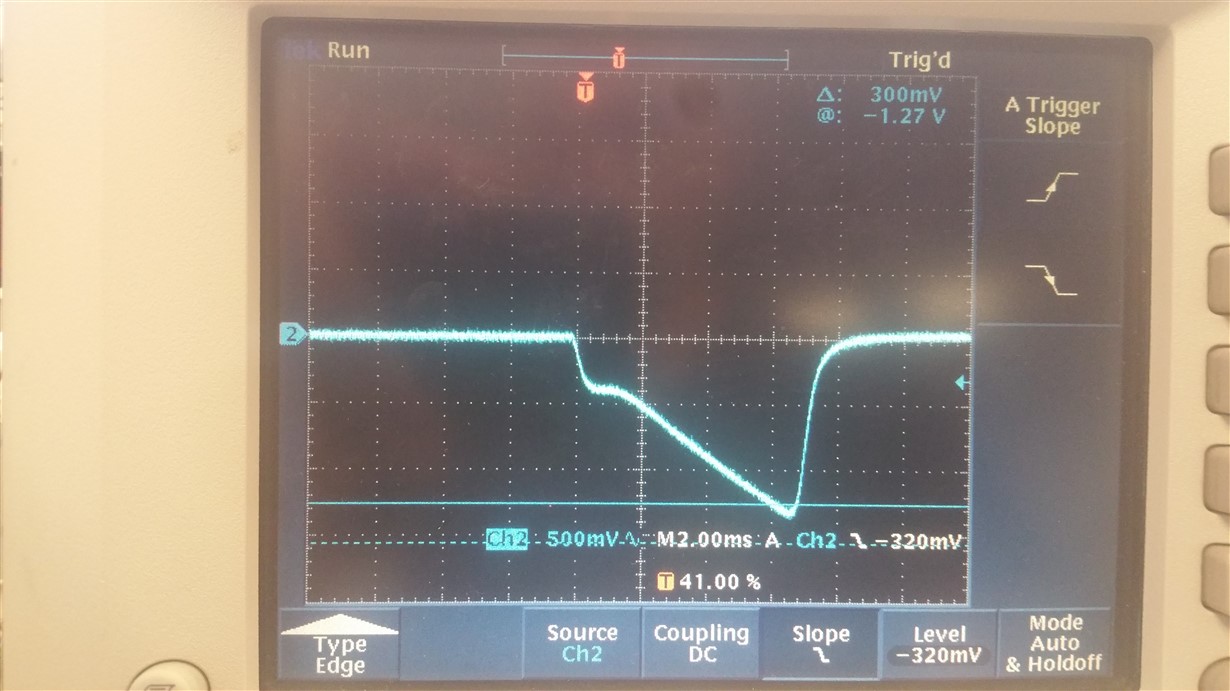
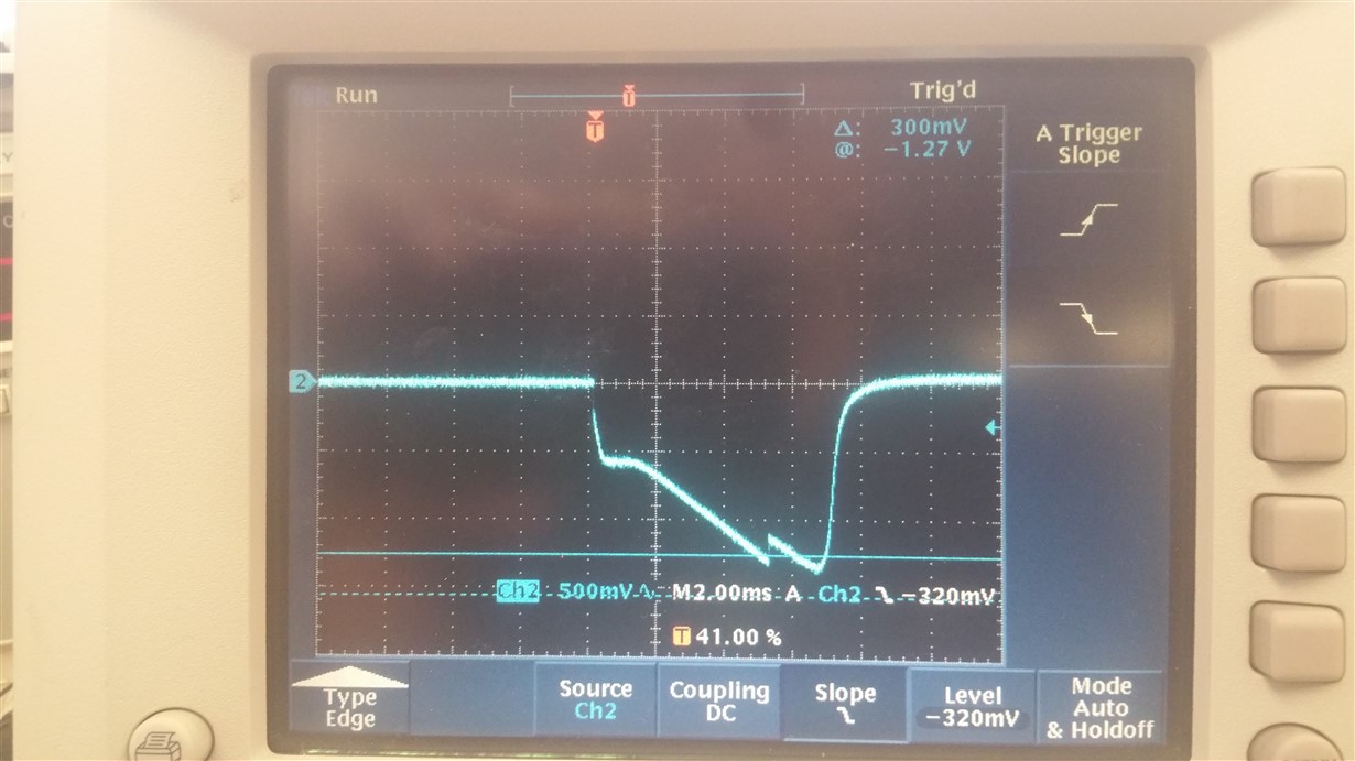
  • For these plots, I have the battery connected. I initially have a DC input to the system, then turn it off.

    The first two plots show the VSYS rail, AC coupled. First zoomed into show the noise waveform, then zoomed out to show that it's at 0.5s/2hz

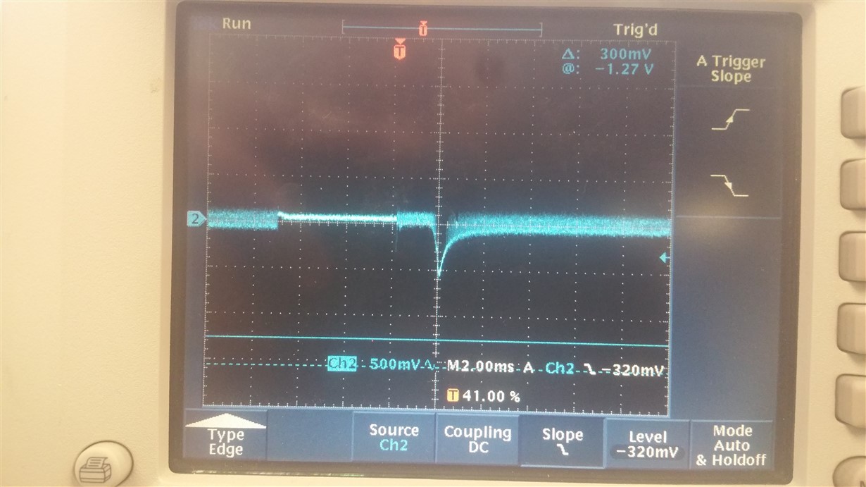
    The 3rd plot shows the unpowered DC input to the charger at the DC_IN_12V net in my schematic

  • All 3 plots are AC coupled. They would all sit at ~13.5V (DC_IN voltage) when DC coupled
  • Manmeet,
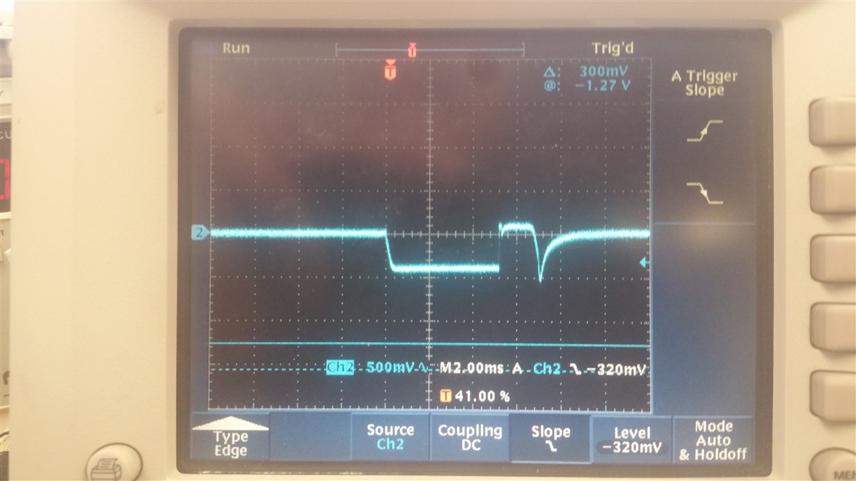
    This has been very helpful. Can you take one more snap shot of the transient noise on SYS, BAT, VACS and VAC pins at the same time during the 0.5 Second sample.
    We agree it may be the extra capacitance on the input. We are looking for a potential register adjustment that may help with this. We need to compare timing to see what is happening first.

    Thank you for working with us on this. Your patience is appreciated.
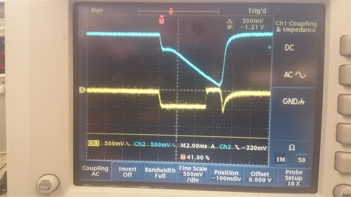
  • This may be more useful: All of the above with respect to DC_IN_12V

    SYS

    BAT

    VACS

    VAC

  • Manmeet,
    That's awesome, thank you. I'll get back with you asap.
  • Manmeet,
    After talking to the system engineers about this part, we have some information for you. This part was designed to work with a power supply module. The VAC sense circuit was created to detect the presence of an external power supply.
    Under the Description
    The TPS65090A device is a single-chip power management IC for portable applications consisting of a battery charger with power path management for a dual or triple Li-Ion or Li-Polymer cell battery pack. The charger can be directly connected to an external wall adapter.
    This explains why the presence of capacitance at VAC prevents the chip from detecting the loss of voltage and keeping the VAC input turned on. Operating from a wall supply is mentioned several times in the data sheet. I also wanted to point out that the SYS output is designed to supply power to the DC-DC converters and LDO's in this chip. The intent is that SYS would have a regulator between it and the load. This also explains why your audio amplifier is hearing the 0.5S sample, as it’s intended to have a regulator after SYS. All indications are that this part is working properly.
    With that being said let's work towards a solution that you can live with. First the VAC input needs less than 6.8uF in capacitance (possibly less, possibly more, but you should be able to test this) to be able to detect the loss of voltage from your supply. You could operate the input buck at its highest frequency and recalculate the capacitance to see if you can get it close to this value.
    Second you could add a series schottky between the TPS54560 and the TPS65090. The diode will prevent the power supply capacitor from charging and VAC should be able to detect the presence of the power supply. You will have a forward voltage drop. Some efficiency loss and you may need to bump up the voltage. You will have to look at this and see if this option is practical.
    Next, you can add more capacitance to the SYS pin. I am not aware of a limit to this capacitance since the SYS pin is the output from the battery and the VAC input. Maybe you can filter out the 0.5 Second samples. Perhaps an RC or LC filter or better yet a PI filter.
    Let me know if this helps. I have one more idea. It’s a bit more work but may work. I can help you with this idea, but I can’t certify it as a solution.
    I am happy to help if you want to talk about other ideas.
  • Thank you for the quick feedback.

    I think the Schottky diode approach will be a good solution for us. We will give this a try.

    I think it would be useful to speak about this input capacitance limitation in the datasheet.

    Thanks!

    -Manmeet