This thread has been locked.

If you have a related question, please click the "Ask a related question" button in the top right corner. The newly created question will be automatically linked to this question.

BQ24600EVM: Non-Operating "Charge Complete" State [/PG LED = LOW & STAT LED = OFF]

Part Number: BQ24600EVM
Other Parts Discussed in Thread: BQ24600

1. I Used "BQ24600 EVM Board(HPA421Rev B)".

2. I Set Parameter Under Circuit.

 1) I Used "3S Li Polymer Battery Pack(500mAh)". So "Vbat = 12.6V" Setting for exchanged R14 - 100Kohm / R15 - 20Kohm

* OUTPUT VOLTAGE *

VOUT = 2.1 * (1 + (100 / 20)
OUTPUT VOLTAGE = 12.6V

 2) I Used "3S Li Polymer Battery Pack(500mAh)". So "Iset = 0.22A" Setting for exchanged R21 - 270Kohm / R18 - 20Kohm / R2 - 0.05

* CHARGE CURRENT *

VISET = (20  / (270 + 20)) * 3.3

COUT  = VISET / (20 * RSR)
            = 0.22 / 1

OUTPUT CURRENT = 0.22A

 3) I Jumper Setting and Input Power 

 - JP1 : BATDRV_IN

​ - JP2 : ACDRV_IN​

​ - JP3 : VREF ON

​ - JP4 : CHGEN ON

​ - JP5 : LED PWR = VPULLUP​

 - Power Supply  : DC15V Input at Charging 0.2A

 ​ 

3. Question

 1) Charge In Progress is OK : (/PG = LOW, STAT = ON)

 2) Charge ERROR is OK : (/PG = LOW, STAT = BLINK 0.5Hz)

 3) Charge Complete is NG

  - Current State : (/PG = LOW, STAT = BLINK Not 0.5Hz)

  - Power Supply State : DC15V Input at Charging 0.2A <-> DC15V Input at non-Charging 0.0A

4. I hope Sloved this Problem. Please Help Yours.

* Wave File (Input Power On)

* Wave File (Stand-By)

  • Can you please describe how are you testing charge complete?

    Also can you provide the waveform on charge current, VFB, VBAT, and STAT when the issue occurs?

  • 1. Can you please describe how are you testing charge complete?
    - I look the LED lamp(/PG and STAT). If charge complete /PG LED is ON and STAT LED OFF.
    - This STAT Pin Definition for bq24600 in Datasheet

    2. Also can you provide the waveform on charge current, VFB, VBAT, and STAT when the issue occurs?
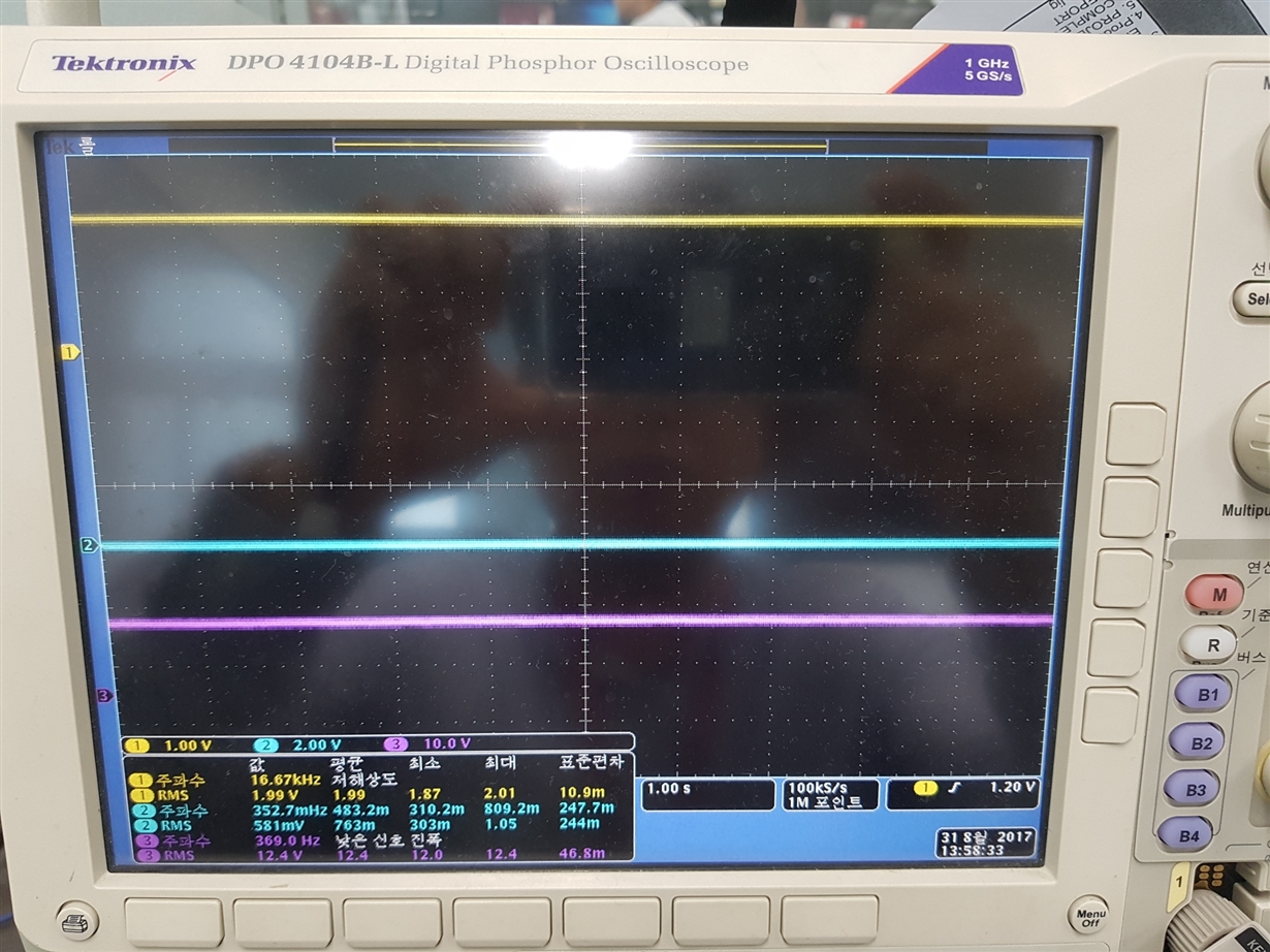
    - Probe1(Yellow) : VFB
    - Probe2(Skyblue) : STAT
    - Probe3(Purple) : VBAT

    1) Stand-by + Battery Pack (NO INPUT POWER, Only Battery Pack)
    - Probe1(Yellow) : 1.99V
    - Probe2(Skyblue) : 0.5V
    - Probe3(Purple) : 12.4V


    2) Input_Power_On + Battery Pack
    - Probe1(Yellow) : 1.8V ~ 2.0V
    - Probe2(Skyblue) : 0.5V ~ 2V
    - Probe3(Purple) : About 12.0V ~ 12.4V


    * So, If Battery charge Complete, Probe2(Skyblue) is 0V(LOW). But Probe2(Skyblue) is changed 0V to 2V

    * Non-Attach Capture file for Waveform.

  • Dear. Jing Zou

    I Mistake clik to more button (to.. spam... ) Sorry. sorry....

  • KyoungSu,

    We are able to see or open your scope capture. We tried to use both Chrome and IE, but neither of them works. Are you attaching the waveform using the "Insert/Edit Media" or "Insert File" button in the tool bar?

  • Jing Zou

    Where is the "Insert/Edit Media" or "Insert File" button in the tool bar?
    I.m not find it.
  • Dear. Jing Zou

    1. Can you please describe how are you testing charge complete?
    - I look the LED lamp(/PG and STAT). If charge complete /PG LED is ON and STAT LED OFF.
    - This STAT Pin Definition for bq24600 in Datasheet

    2. Also can you provide the waveform on charge current, VFB, VBAT, and STAT when the issue occurs?
    - Probe1(Yellow) : VFB
    - Probe2(Skyblue) : STAT
    - Probe3(Purple) : VBAT

    1) Stand-by + Battery Pack (NO INPUT POWER, Only Battery Pack)
    - Probe1(Yellow) : 1.99V
    - Probe2(Skyblue) : 0.0V
    - Probe3(Purple) : 12.4V


    2) Input_Power_On + Battery Pack
    - Probe1(Yellow) : 1.8V ~ 2.0V
    - Probe2(Skyblue) : 0.5V ~ 2V
    - Probe3(Purple) : About 12.0V ~ 12.4V


    * So, If Battery charge Complete, Probe2(Skyblue) is 0V(LOW). But Probe2(Skyblue) is changed 0V to 2V

    3) Input_Power_OFF + Battery Pack  = Stand-By
     - Probe1(Yellow) : 2.00V
     - Probe2(Skyblue) : 0.0V 
     - Probe3(Purple) : 12.4V


     * Thank for your help.

  • 1. Are you using a real battery for testing? Or are you using a e-load? If possible, please test with a real battery to see if the issue still occur.

    2. From the scope capture, it looks like there is a lot of voltage drop from charging to no charge. Can you please make sure that the cable connecting from the battery source to the EVM is as short as possible?

    3. Is there any system load connecting in parallel with the battery? There are three levels of the VBAT and VFB voltage from the scope capture with the issue. This pattern does not look like being caused by the charger. Please remove the load when testing. 

  • Dear. Jing Zou

    1. Are you using a real battery for testing? Or are you using a e-load? If possible, please test with a real battery to see if the issue still occur.

     A : Yes, I Used Real Battery.

    2. From the scope capture, it looks like there is a lot of voltage drop from charging to no charge. Can you please make sure that the cable connecting from the battery source to the EVM is as short as possible?

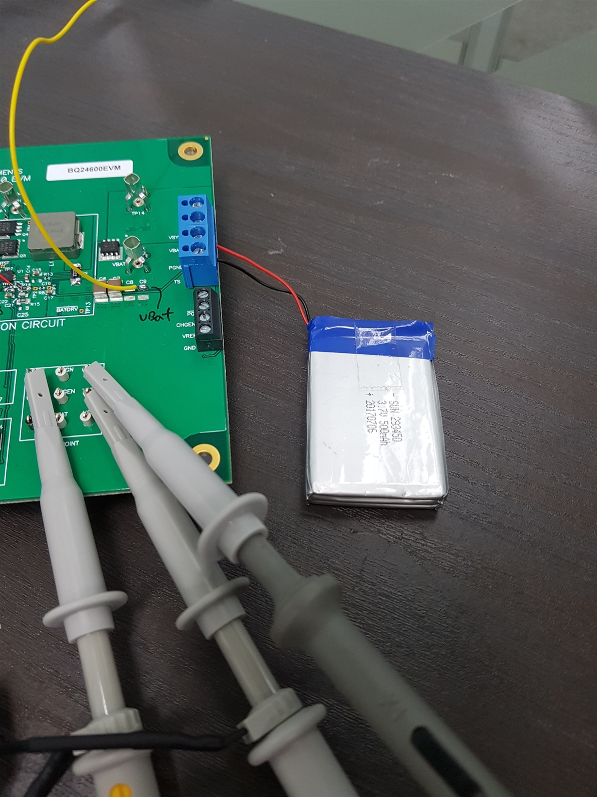
    A: EVM to Battery short.

    3. Is there any system load connecting in parallel with the battery? There are three levels of the VBAT and VFB voltage from the scope capture with the issue. This pattern does not look like being caused by the charger. Please remove the load when testing. 

    A: I always no load,

    Only Power Supply -> EVM -> Real Battery Pack in Test.

    Maybe, Operation PCM Circuit in Battery Pack?? ........

  • Do you have captures on the charge current? 

    All the conditions I have mentioned above is based on the assumption that the battery internal impedance is stable. However, it is also possible that the battery cell impedance change causing or the protection circuit inside the battery pack causing the issue.