This thread has been locked.

If you have a related question, please click the "Ask a related question" button in the top right corner. The newly created question will be automatically linked to this question.

LM5104: LO signal

Part Number: LM5104

My input signal is 1MHz, 50% duty cycle, square wave.

Output load is no load or PZT load.

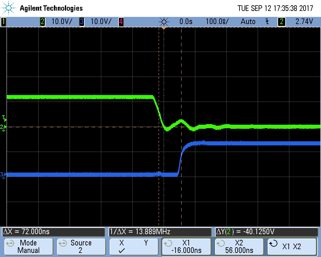
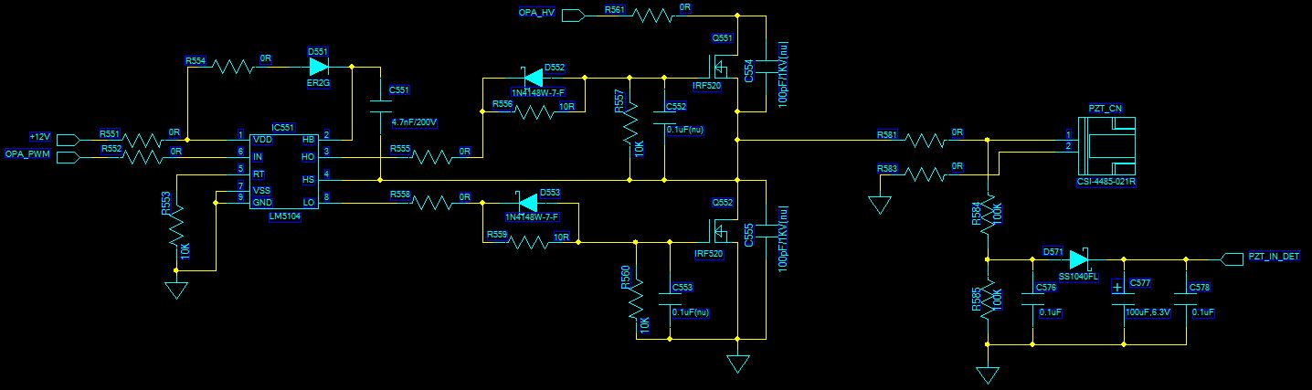
When OPA_HV voltage <5V, the HO and LO signal is good.

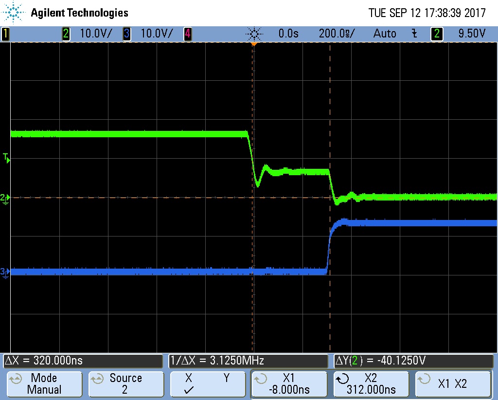
But, OPA_HV voltage >5V, the LO turn on time is decrease 100ns, HO signal turn on time is no change.  

I do not know why. 

  • Hello Mario,
    Thank you for your interest in the LM5104, I am an applications engineer with TI and will work to address your concerns.
    To better understand what may be the cause of the LO on time change you see, I have a few questions.
    Can you confirm that the dead time resistor value is 10K as shown in the schematic?
    Can you confirm the dead time is as you expect with the dead time resistance? 10k will be ~90ns nominal.
    Is the dead time as you expect when OPA-PWM is <5V, or >5V.?
    Can you confirm if the dead time resistor is located close to the IC, with short trace connections to RT and GND?
  • Thank you for your reply.

    1. The dead time resistor value is 10K Correct.

    2. I measure the dead time is 72ns. (OPA_HV=0V) (Port2 : HO, Por3 : LO)

    3. I measure dead time.  (OPA_HV=6V) (Port2 : HO, Por3 : LO)

    4. R553 is RT. 

  • Hello Mario,
    Thank you for the scope plots and board layout plot. I want to confirm the conditions of the plots as I understand.
    For the 1st two plots, the dead time of LO falling to HO rising and HO falling to LO rising is 72ns with the HV input=0V.
    On the 2nd two plots, the dead time of LO falling to HO rising is 72ns, and the dead time of the HO falling to LO rising is 320ns with the HV input=6V. Please confirm this is correct.
    On the board layout, R553 looks close to the driver IC with a short RT connection. On the ground connection, is the light green large trace ground with R553 and the LM5104 connected with vias? Also if the large green trace is ground, is this trace conducting high switching currents and connected to the power train ground?
    Also, on the schematic, or layout I do not see the VCC capacitor. Can you indicate where the VCC bypass capacitor is located.
    If there is VCC noise or ringing, or ground ringing this could affect the dead time timer.
    Also in the LM5104 datasheet I see the power pad is connected to the ground pin on the example layouts. Can you confirm if the power pad is connected to ground on the PCB layout?
    Some experiments to try would be: locate the VCC bypass capacitor close to the IC VCC and VSS pins, connect the power pad to the VSS pin. Move R553 and solder directly to pins 5 and 7 of the LM5104.
    Let me know if any of these suggestions help with the timing.

    Regards,
    Richard Herring
  • Hello Richard,

    Thank you for your reply.

    1. For the 1st two plots, the dead time of LO falling to HO rising and HO falling to LO rising is 72ns with the HV input=0V.

    On the 2nd two plots, the dead time of LO falling to HO rising is 72ns, and the dead time of the HO falling to LO rising is 320ns with the HV input=6V. It's correct.

    2.The light green large trace ground with R553 and the LM5104 connected with vias is correct.  

    The large green trace is ground and this trace conducting high switching currents and connected to the power train ground, correct.

    3. The VCC capacitor is not be design in schematic and layout, I solder directly to VCC and VSS.(0.1uF and 10uF).

    4.I try move R553 and solder directly to pins 5 and 7 of the LM5104. But the result is the same( HO falling to LO rising is 320ns with the HV input=6V).

  • Hi Mario,

    I was reviewing threads on e2e, and I noticed we didn't close this one out with you. I apologize for that.

    Have you figured out this issue, or do you still need our assistance? If so, how can we help?
  • OK, I figured out this issue.
    Thanks!
  • Hello Mario,

    Thank you for the confirmation that you resolved the issue with the LM5104. Can you comment on what changes you made to the design to resolve the issue? This will help with others who have similar issues with their designs.

    Regards,

    Richard Herring