This thread has been locked.

If you have a related question, please click the "Ask a related question" button in the top right corner. The newly created question will be automatically linked to this question.

TPS53014: Dead time and FET turn on/off delay time

Part Number: TPS53014

Hello,


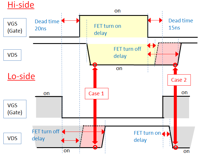
Regarding to the dead time(below) on TPS53014, my customer is asking a question.


The turn on/off delay time of external FET which they will use are following.


(Question)

About FET turn on/off delay time,

If these time exceed the dead time, it is possible that 2 FETs (high/low side) become “ON” at same time.

As a result, FETs might be destroyed by the shoot-through currents.

When choice external FET, they should need to consider the turn on/off delay time.

(These need less than the dead time.)

My understanding is correct?

Could you please give advice or comment about choice external FET?


Regards,

Tao2199

  • Tao,

    I would not worry about this for fet selection. The controller has built in dead time delay. The fet delays add on top of it so practically if you pick a fet with longer turn on delay then you would effectively more dead time, less efficiency. Size the fets for your current needs and efficiency primarily. The drive voltage for the fets is 5V so fets that have low Rdson at gate voltage less than 5V or logic level fets would give best efficiency.

    Regards,

    Mathew

  • Hello Mathew,


    Thank you for reply.

    I understood that the fet delays add on top of dead time.

    And I have additional two question.

    (Question)

    (1) Which side does the dead time have? (Hi-side or Lo-side?)

    (2) If FET turn-off delay time exceeds total delay time(dead time+FET turn on delay),

    I guess that it is possible that 2 FETs (high/low side) become “ON” at same time.

    (Please refer below(case1 and case2).)

    I think that FET turn-off delay time might needs less than the dead time.)

    Could you please give opinion or comment?


    Regards,

    Tao2199

  • Tao,
    1)Yes the dead time is for both (Low->High->low)
    2)Yes typically the controllers pull up current and pull down current are strong to make sure the fet rise and fall times are faster than the dead times. You can calculate this by I=Cdv/dt, where I = pull up or pull down current, C =fet gate capacitance,dv=swing in the gate voltage and dt is the time, you solve for dt. If you pick very high capacitance fets with weak drive currents yes you can run into problems you are describing.

    Regards,
    Mathew
  • Hello Mathew,


    Thank you for reply.

    I have informed to my customer about your comment.

    They are asking one question.

    ・Do you have maximum/minimum data of dead time?

    But according to datasheet, these data are ensured by design.

    Is it possible to see these data?


    Regards,

    Tao2199

  • Generally if the datasheet says "ensured by design", that means we do not have characterization data to share.