This thread has been locked.

If you have a related question, please click the "Ask a related question" button in the top right corner. The newly created question will be automatically linked to this question.

LM2841: LM2841 repeatedly failing with smoke

Part Number: LM2841

Hi,

I just had the third one of these (LM2841XMK-ADJL) blowing up in my application, and I am failing to find the root cause.

It should not be an overvoltage situation, as there is a 28V SMBJ suppressor diode on the input. The capacitive load at the output of the converter is approx 20uF, and current draw is only some tens of mA. I hope that someone can check my design. Here is the schematic:

Cheers

Frank

  • possibly it is due to the FB connection. It should be after L4 not after L5.
  • Hi John,

    I understand what you mean, I'll change that in a redesign. Anyhow, L5 is only a small (0603) ferrite bead with some hundred nH... I checked the output voltage overshoot during startup at 12V and 30V:
    www.kicksurfer.de/.../startup_VIN_12V.png
    www.kicksurfer.de/.../startup_VIN_30V.png

    I cannot see any sign of instability here that could cause this failure.

    I also checked all other voltages: VIN (flat), SHDN (clean, fast, approx 3V), FB (no ringing), SW (no ringing), CB (no ringing).

    The only suspicious thing that I found was a strange behavior of the switch. It seems that the controller triggers the MOSFET, even when the CB voltage has not developed yet. This picture was captured at the CB pin immediately after enable:
    www.kicksurfer.de/.../CB_VIN_30V.png

    Cheers
    Frank
  • Hi John,

    I just had replied, but I cannot find any evidence of my reply. Did you receive it?

    Cheers
    Frank
  • Check the input voltage and the SW node. Use tip and barrel method or short (<1cm) gnd lead. Use full BW. Look for suspicious transients , overshoot, undershoot or ringing. Also make sure the SW pulse stream is stable.

  • The pictures were taken with 300MHz bandwidth, for the switch node I used a low inductance spring clip to ground the probe. No sign of overshoot. And 30V is far away from the max rated 42V of that device. The input voltage is also steady. There is a massive path from three low-ESR 470uF capacitors to the circuit above. Plus massive multilayer ground planes.

    The chips keep blowing as soon as they are enabled through SHDN.
  • Mostly,these type failures are caused by over voltage.  Can you post your PCB layout?

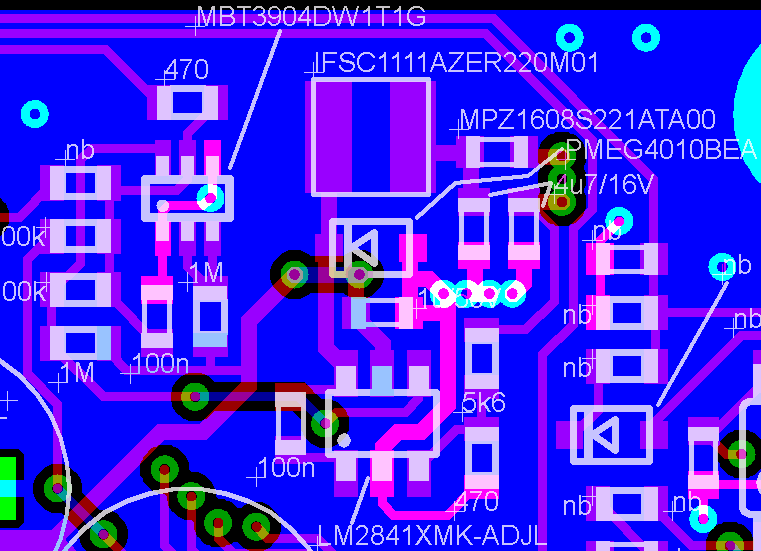
  • Sure, here it is. Red is top, blue is bottom (solid GND). Another inner layer is solid GND as well. I highlighted GND here.

    Cheers

    Frank

  • While that layout is not ideal, I don't think I see anything specific that would cause the IC to fail repeatedly. Let's see what the direct support person for LM2841 has to say about it. I will notify them.
  • Hi Frank ,

    Is the failure repeatable ?

    Just to verify can you please connect SHDN pin to VIN and recycle the VBUS voltage . This will help in isolating the issue . Also as John mentioned please take the feedback after L4 and not L5 .

    ---Ambreesh
  • Hi Ambreesh,

    I am afraid but I do not have a setup that repeat the failure with a reasonable probability. The failure happens infrequently. And it has never happened when applying input power (VIN). It always happens when the flip flop in my circuit above enables the LM2841. And all the oscilloscope diagrams that I have posted are related to this event. And there is a large 30V suppressor diode at VIN that prevents overvoltage from ringing when connecting the main (25.2V) battery. I would say that I can exclude an overvoltage to the LM2841, I am sure that it is something different. What about that spurious MOSFET turn without sufficient boost voltage that I showed in an earlier post?

    Cheers

    Frank

  • Frank ,

    What is W supply in the Schematic ? During Startup is there a instance where potential at SDWN pin exceeds potential at VIN ?

    Further is it possible to test the boards with SDWN tied to VIN and power cycling the VIN .

    You may also want to add some capacitance to SDWN pin too.

    ---Ambreesh
  • W is one of the phases of a BLDC motor. Its rotation wakes up the board.

    I could successfully relate the problem to overvoltage now. I got confused by the fact that enabling the device would bring it to failure. It gets damaged when main power is connected through very long leads (the suppressor diode has a too high clamping voltage (SMBJA36)). However, it does not pop at this time. This is delayed until the shutdown is released. I have changed to SMCJ28A in the design, these successfully clamp the input voltage well below 40V.

    Thanks for your support!

    Cheers

    Frank