This thread has been locked.

If you have a related question, please click the "Ask a related question" button in the top right corner. The newly created question will be automatically linked to this question.

TPS92512HV: TPS92512H

Guru 13485 points
Part Number: TPS92512HV

Got below/attached:

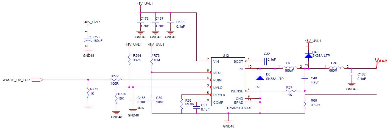
We have a design problem with TI’s TPS92512HV chip.

 We are working with 48V input and want to work with 32V@350mA output (for the UV leds).

Unfortunately, we didn’t succeed  to reach the 32V output only to 28V.

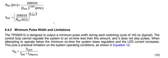
In the datasheet we note the Fsw need to be between 100kHz-2Mhz.

When we tried to change Rrt (to 19.8KOhm) to get 32V according to the formulas, we have 4.7MHz Fsw. 

The equation below:

Pls, we need your help with our design to get the desirable results.

 Attached the datasheet and our design.

( note: in the attached design with Rrt=69.8kOhm we reach the same 28V output)

  • Hello Eli,

    The equations in 8.4.2 is simply a limitation for VIN to VOUT differential if you need to switch at a high switching frequency. But it should not be used at all to choose RT. Realistically 2MHz is the max due to the FET drive requirements, but 1MHz is more realistic of a max, and the higher the input voltage the lower you generally want to go (AC losses are directly proportional to Fsw and VIN^2). So with 48V input you probably want to stick to 500kHz or below for thermal reasons, and with a 100uH inductor (I hope, it says 100uF in the schematic) you should be just fine with 500kHz or below and will be much more able to regulate correctly. At 4.7MHz it is likely not able to drive the FET sufficiently.

    Try lowering Fsw to 300kHz to 500kHz and see if that helps.

    Regards,

    Clint

  • Hello Clint

    Thanks!!

    One more question I got :

    I try to drive 8 serial LEDs(datasheet attached) with 350mA.

    I calculate my Rsense according to equation 8.

    Vsense= 220mV

    ILED= 350mA

    Rsense need to be 0.62Ohm (I solder 0.6 resistor and the current need to be 367mA)

     When I measure the current to the LEDs I have only 220mA@28V output ( if we consider Vsense=300mV the amperage need to be 500mA).

    (BTW, in the PS display I saw 330mA@48V)

     By changing the Rsense to 0.4Ohm the amperage was 240mA@28V.

     Can u pls explain why I didn’t get the desirable voltage by changing Rsense according to the formula?

  • HV-F5901UVTWCXA v1 0.pdfAdding related LED D/S

  • I try to assemble 0.33Ohm and with 300mV Vsense (I supposed to see 900mA) is saw 390mA..

    Ignore the 220mV I wrote, Vsense is 300mV.

    Thx a lot!
  • Hello Eli,

    Can you let me know what switching frequency you are using? Also, what is the inductor part number you are using? Your input current being higher than your output current is not right for sure, so something strange is going on.

    Thanks,

    Clint