This thread has been locked.

If you have a related question, please click the "Ask a related question" button in the top right corner. The newly created question will be automatically linked to this question.

TPS54386: TPS54386 EMC problems - 50 MHz harmonic

Part Number: TPS54386

Dear TI,

My name is Bruno and I'm from Argentina.

I have designed a product which use TPS54386PWPR to provide 5v and 6v. The first one is for digital modules and the second one for a small air compresor controller.

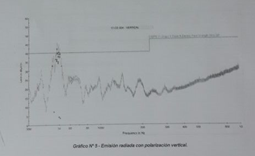
The thing is we made measure the emitted radiation and we have a peak around 50 MHz, exceeded allowed limits for this kind of product. This is the measure of the laboratory report:


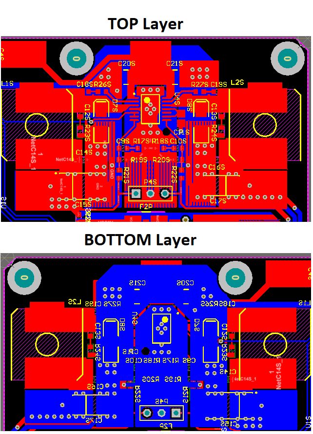
We made our test with a RF explorer loop probe (https://www.digikey.com/products/en?keywords=1597-1409-ND) and found the emission over the TPS chip so we want to ask if there's any workaround or known issue reported? The Schematic and Layout are:
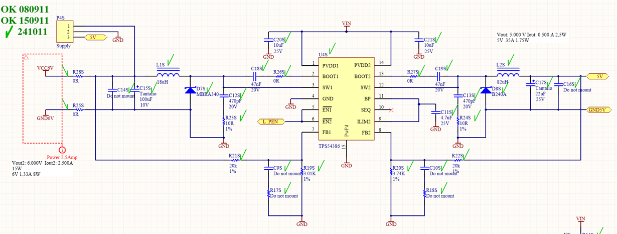
The main peak of the radiation is on top of U4S (TPS54386) and decrease slightly at the inductors. Beyond this module the radiated peak decrease significantly.

We know one solution could be shield this module in order to improve EM emission but we want to try solve it with the minimum parts adition. If not we have to make a new PCB and all tests again and this is (a lot of) time and money.

Thank you in advance for your time.

Best regards,

Bruno

  • Hi Bruno,

    Noise at this frequency suggests it is coming from the SW node rising/falling edges. Luckily you have included place holders for BOOT resistor in series with the BOOT capacitor to slow down the edges. Something you can try is to replace the 0 Ω resistor with a 1 Ω to 3 Ω resistor.

    Since you are trying to keep it to a component change only, I suggest also trying different catch diodes. Different schottky diodes have different reverse recovery behavior and could contribute to more radiated noise from the buck converter.

    Best Regards,
    Anthony
  • Hi Anthony,

    Thank you so much for your answer.

    We made some test increasing RBoot and found a little decrease on EMI when we use 8.2 ohms. Could you tell me the consecuences of increasing this value? Do you think will affect the regulation? Device is battery powered from 12v lead-acid battery or 18v external power supply.

    We will change the diode in order to improve recovery time.

    Best regards,

    Bruno
  • Hi Bruno,

    For now I would be hesitant to go beyond the 3 Ω recommendation on the datasheet. I was not involved with putting this limit into the datasheet but I'm sure it's there for a reason. It will be hard for me to say exactly what the consequence of going higher will be but it would be something like the following. The larger BOOT resistor will cause a larger drop in the BOOT voltage at turn on of the high-side MOSFET. A large enough drop has potential to cause glitches in the control circuit which would result in unstable like behavior at the switching node.

    Instead of increasing the BOOT resistance above 3 Ω, you could try increasing the strength of the SW node snubber. This is done by increasing the capacitance in the snubber from 470 pF. You may need to tune the resistor too to better optimize the snubber. You can either use the EMI measurement or a SW node measurement to judge which value works best.

    There is another thing to try but this would result in a schematic and PCB change. I didn't make this recommendation initially because I know you would like to avoid this. If you add a lower value ceramic capacitor next to each PVDD pin it could better bypass the 50 MHz to help reduce the noise at this frequency. The ceramic capacitor should be chosen so it's resonance frequency is near the frequency of the noise you want to filter (50 MHz). I checked muRata's website and a 18nF-22nF capacitor should have a resonance frequency near 50 MHz. These capacitors should be in addition to what's already there.

    Best Regards,
    Anthony

  • Hi Bruno,

    Did you end up finding a solution to this?

    Anthony
  • Hi Anthony!

    Not yet. Components are coming, so we will have to wait till next week. Then we will take a consulting with RF Lab in order to test your recommendations and some other modifications we introduce.

    I'll let you know the results of the test, I'll promise.

    Best regards,

    Bruno