This thread has been locked.

If you have a related question, please click the "Ask a related question" button in the top right corner. The newly created question will be automatically linked to this question.

UCC28063: Tset resistor change

Part Number: UCC28063
Other Parts Discussed in Thread: UCC25600

hi 

My client configured a 270W power circuit with UCC28063 + UCC25600.

The customer confirmed that the FET did not turn on during the input impulse test.

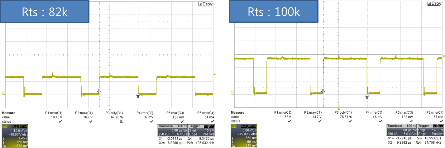
To improve this, we changed the resistance of TS pin from 100k ohm to 82k ohm. After that, it seems that the problem has improved somewhat.

The customer is asking if there are any additional considerations when changing the TS resistance.

On the datasheet
TSET resistor to program PWM on-time is from 66.5k to 400k.

The figure below shows the GDA voltage before and after the change.

vin : 90V

  • Hello Andy,

    What sometimes happens during an impulse test is that noise gets coupled onto the TSET pin.
    TSET has a feature that the UCC28063 latches off if TSET goes open circuit and the impulse noise can cause TSET to momentarily go open circuit and cause a shutdown. You can :
    (1) Check your layout and make sure the TSET resistor is placed directly between TSET and AGND
    (2) Add a small capacitor on TSET
    (3) Evaluate the pcb layout and enclosure and see how the impulse noise is coupling to the UCC28063

    The value of the TSET resistor is chosen based on the maximum required on time of the converter. Your waveforms show a change from 82k to 100k and that probably wont cause much of a difference But you should be aware of the possible increase in power capability during a fault condition

    Regards

    John