This thread has been locked.

If you have a related question, please click the "Ask a related question" button in the top right corner. The newly created question will be automatically linked to this question.

TPS62136: Startup behavior and load capacitance

Part Number: TPS62136
Other Parts Discussed in Thread: TINA-TI

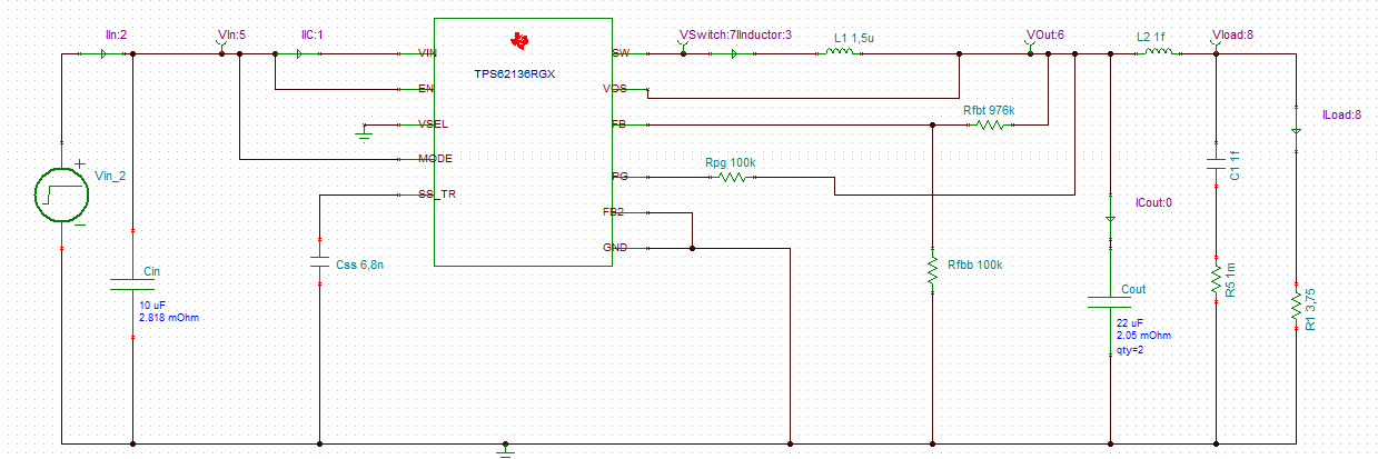
While looking for a solution for a 12V in (nominal) 7.5V@2A out DC/DC, I found this part. Compared with some other I tried before it on Webench and TINA-TI, this one offers an excellent transient response.

The simulations on TINA raised the following questions:

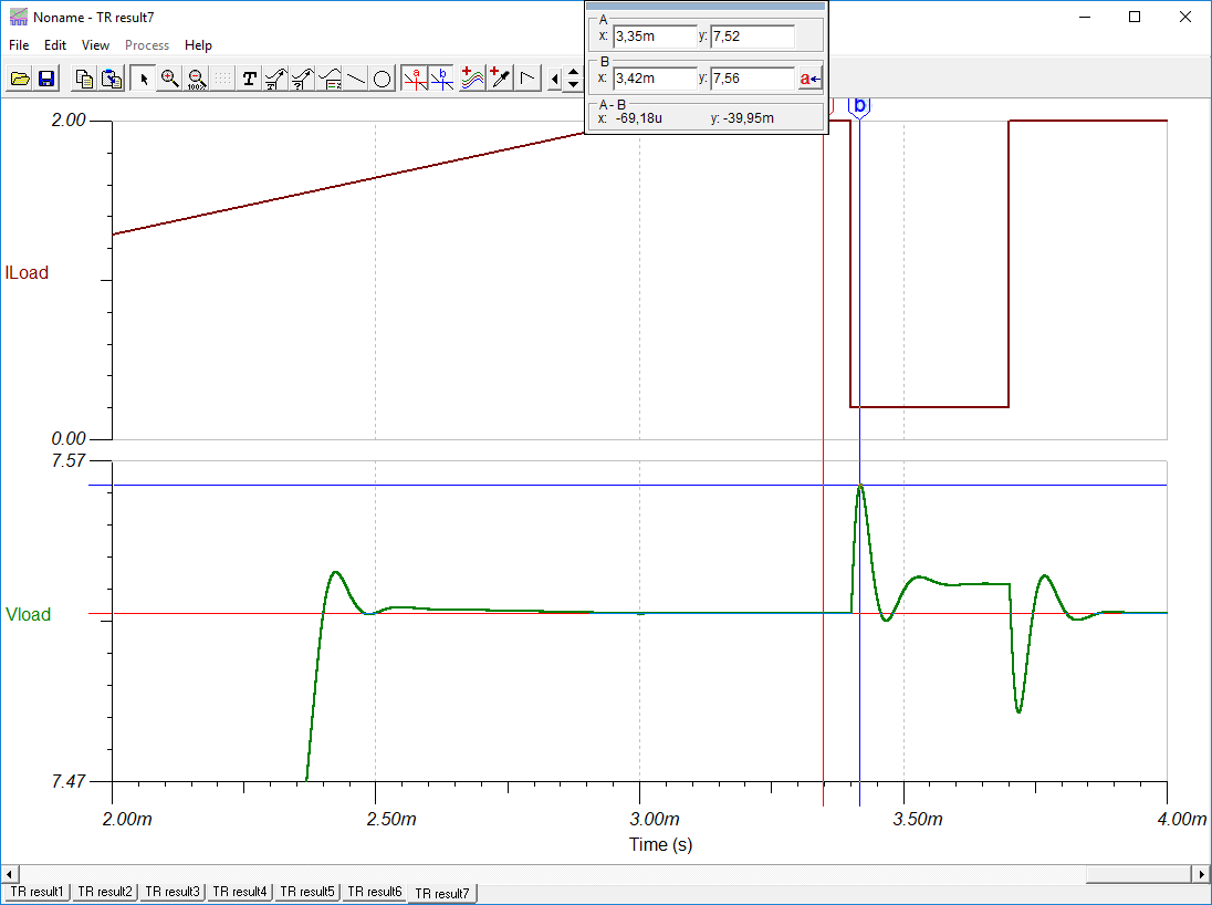
1- The startup has an inflexion on Vout at 1.5 ms (nominal soft-start time is 1.9ms). That makes startup to extend beyond the nominal. Is it normal? Note: if you extrapolate the initial part of the output voltage before the inflextion, the startup time is around the nominal.

2- I need low ripple and as stable an outuput as possible. Besides the design requires many capacitors and I used 400uF to simulate the supply. This capacitance is the very reason I needed to increase the soft-start time as the converter would not start properly with Webench default setting (0.6ms). The simulation shows a good transient response (~40mV for a 1.8A step, L2=100nF, Cout=400uF) and it stabilizes quickly. Also the high frequency ripple after the 0.1nH inductance is pretty low. So I would like to check I may rely on the simulations results to make the decision about using this part for this DC/DC converter.

I am attaching the TINA-TI file I used to simulate the transient behavior.

PS-7_5_2A-startup-180108a.tsc

  • Hi Elder,

    Thanks for finding this part and glad the simulations were useful. Yes, DCS-Control is a very fast response topology.

    Let me check with our modeling team on #1. I don't see this in the actual waveforms in the D/S, figures 61 and 68.

    I didn't see a question in your #2. Modeling is a good tool to get started, but you need to validate actual hardware (your own prototype or an EVM) to make sure a design is suitable for your system.
  • Hi Chris,

    First of all, thank you very much for your quick response.

    Re #2, you're right, I forgot to ask the question: is it OK using high load capacitances with it? As it would not start (in simulation) with the high load capacitance and low soft-start time (I believe the current limiting circuit acts), I started worrying about being using it (in)correctly.

    Regarding your last comment, I totally agree, simulation is not a substitute for prototyping, I just wanted to check if this is a good path to follow (i.e. this IC is good for the requirements I have).
  • Hi Elder,

    Yes, Table 2 shows the recommended output capacitance values with more details upon clicking the link in note 3.

    With too short a SS time, it might reach current limit and hiccup. You should be able to confirm this by looking at the inductor current in the simulation.

    Yes, this IC is an excellent and simple choice for your power requirements.
  • Hi Elder,

    We are looking into the model for your query mentioned in #1 and will get back to you with in couple of days.

    Regards,
    Saket
  • Hi Elder,

    Reply to your query number 1:
    The change in the nature of soft start is not observed in the silicon result of the device. In IC it is same as per the calculated value from the datasheet.
    This different nature of soft start might be included in the model to avoid a glitch in VOUT when the linear SS ramp saturates.

    Thanks,
    Vivek Agarwal