This thread has been locked.

If you have a related question, please click the "Ask a related question" button in the top right corner. The newly created question will be automatically linked to this question.

WEBENCH®工具/ TPS63002: TPS63002 Large starting current

Part Number: TPS63002
Other Parts Discussed in Thread: TPS63000

Tool/software: WEBENCH® Design Tools

Hi All,

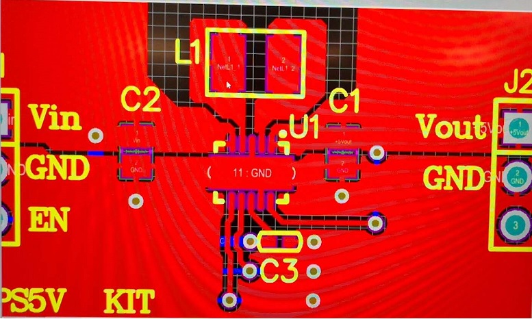
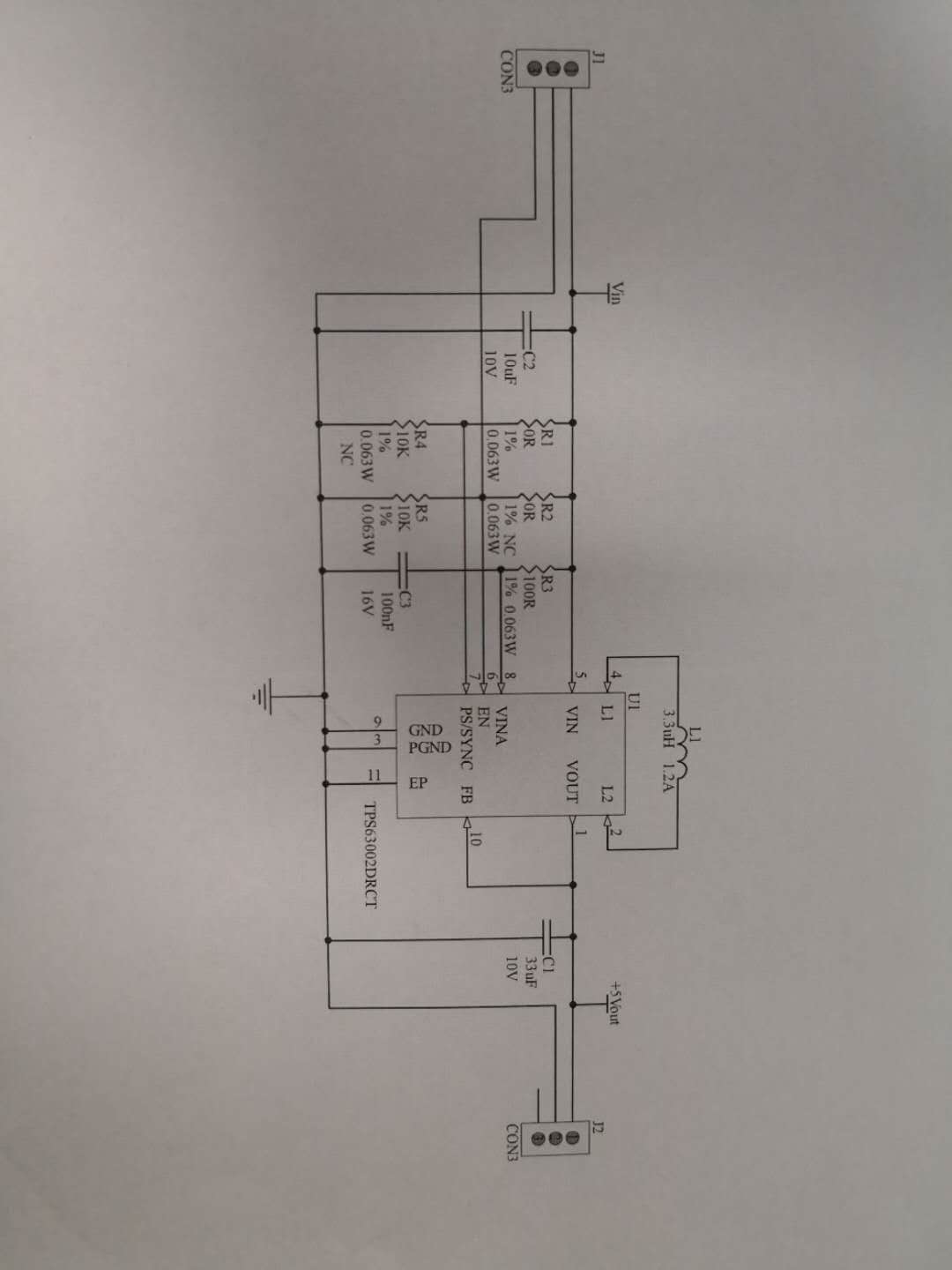
I used TPS63002 to design the input voltage 4.75v~5.25v output voltage 5V Current 1 A circuit, the schematic diagram is as follows:

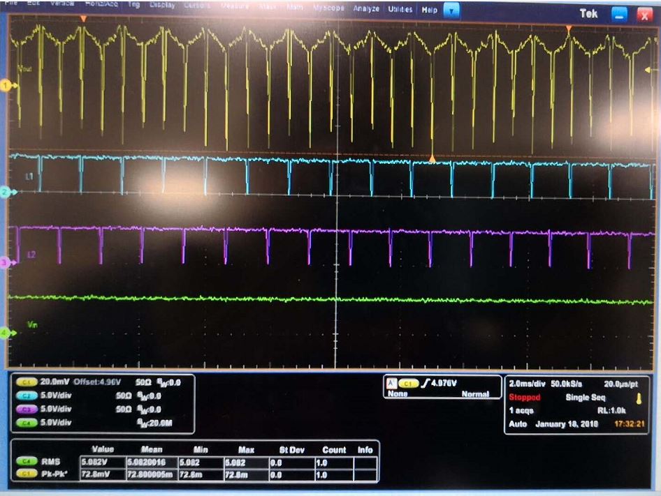
The test diagram is as follows:Output no-load, first to input and then start en, the figure on the current is input current, how to reduce the start-up current, Thanks.

  • Hi Charles,

    The start up current can be controlled by adding the very simple "soft start circuit" as described in this app note: www.ti.com/.../slva553.pdf
    For that it is required to use the adjustable version of this IC: TPS63000

    What is the end application?
  • Hi Sabrina,
    About soft start, I am using the TPS63002 fixed output 5V voltage, can not use this circuit as the example, is there a better way?
  • HI Charles,

    As mentioned earlier, it is necessary to use the adjustable version of the device TPS63000 to implement the soft start circuit.
    What is the main concern about using the adjustable version?
  • Hi Sabrina,

    Another problem with load, Output voltage of 5V 500ma, Input voltage of 5.28V, measured voltage is as follows, Peak voltage Severity, the circuit needs to be adjusted?

  • I think you may need to adjust your oscilloscope settings. The sample rate does not match to the signals you try to measure.

    Can you please rephrase your last question? I did not understand what you mean with "Peak voltage Severity, the circuit needs to be adjusted?"
  • Hi ,

    My problem is that the Mark 1 is output voltage waveform, Mark 2 is L1 angular output voltage waveform, Mark 3 is L2 angular output voltage waveform, Mark 4 is input voltage waveform, customer thinks output voltage fluctuation is more than 80mV, ask if there is optimized space.

  • I assume you want to measure/improve the output voltage ripple. Looking on your oscilloscope settings i think you are still not measuring it properly. The switching frequency of this device is at least 1.25MHz. You set the sample rate to 20us/pt which means for this device you have 1 sample point in at least 25 switching cycles. It looks like your measurement setup captures switching noise which is inductive coupled into the GND loop of your probes. The sample rate settings and the filtering you have set may cause those dips in the output voltage waveforms at the time of the switching edges.

    Reducing the ripple of the output voltage in general can be done by increasing the output capacitance or adding additional filter stages. Before doing that I recommend to improve the measurement setup. For that I suggest to measure the output voltage only, with only 1 probe connected to the oscilloscope. This probe should be connected directly at the output capacitor with short connections, using no long GND wire as the oscilloscope probes have it by default.