Other Parts Discussed in Thread: PMP9622, , TL431, PMP
Hi Team
My customer is curious about the different feedback circuit (EA+ EA- EAO) between PMP9622 and UCC3895EVM-001
why we designed two types of feedback circuit, any different and which one is better?
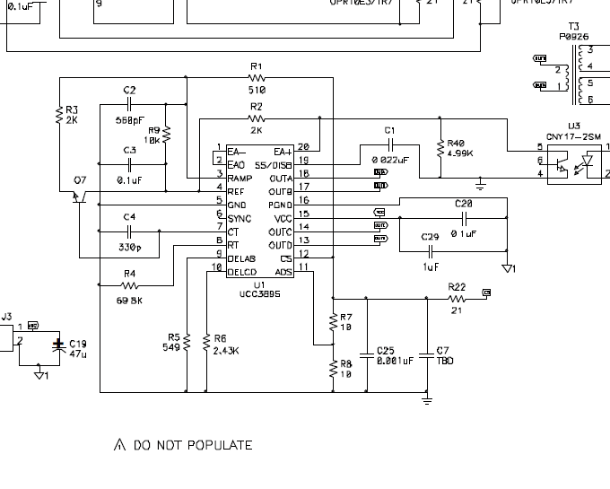
PMP9622
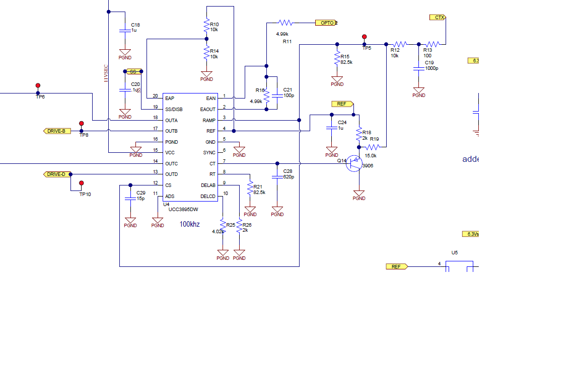
UCC3895EVM-001
EA- and EAO are connecting each other,