This thread has been locked.

If you have a related question, please click the "Ask a related question" button in the top right corner. The newly created question will be automatically linked to this question.

WEBENCH® Tools/LM5085: Output voltage not controlled

Part Number: LM5085

Tool/software: WEBENCH® Design Tools

Hi,

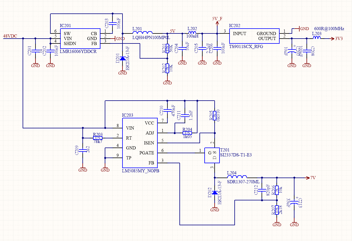
I designed with WeBench a simple Buck controller for my application.

I need three voltage output. 5V, 3V3 and 7V - 1.5A. The supply voltage is +48Vdc battery.

5V and 3V3 works fine. I've a problem with 7V (LM5085 controller).

The schematics below respect the values calculated via webench. I change only D202.

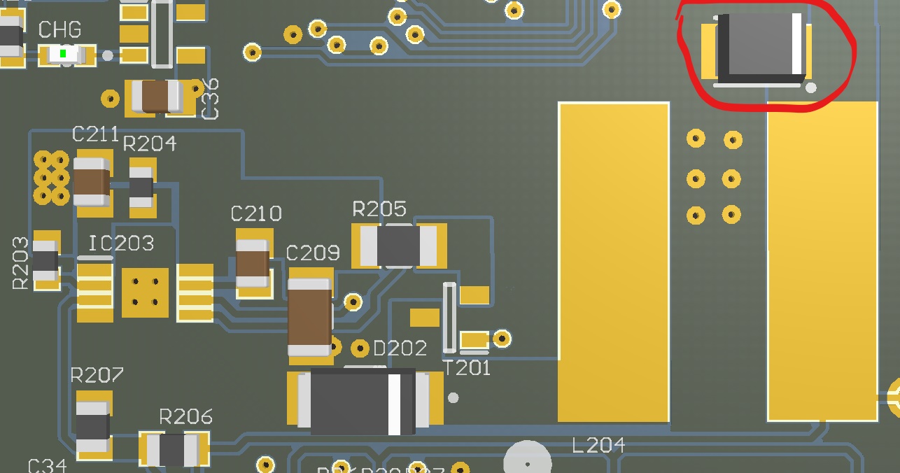
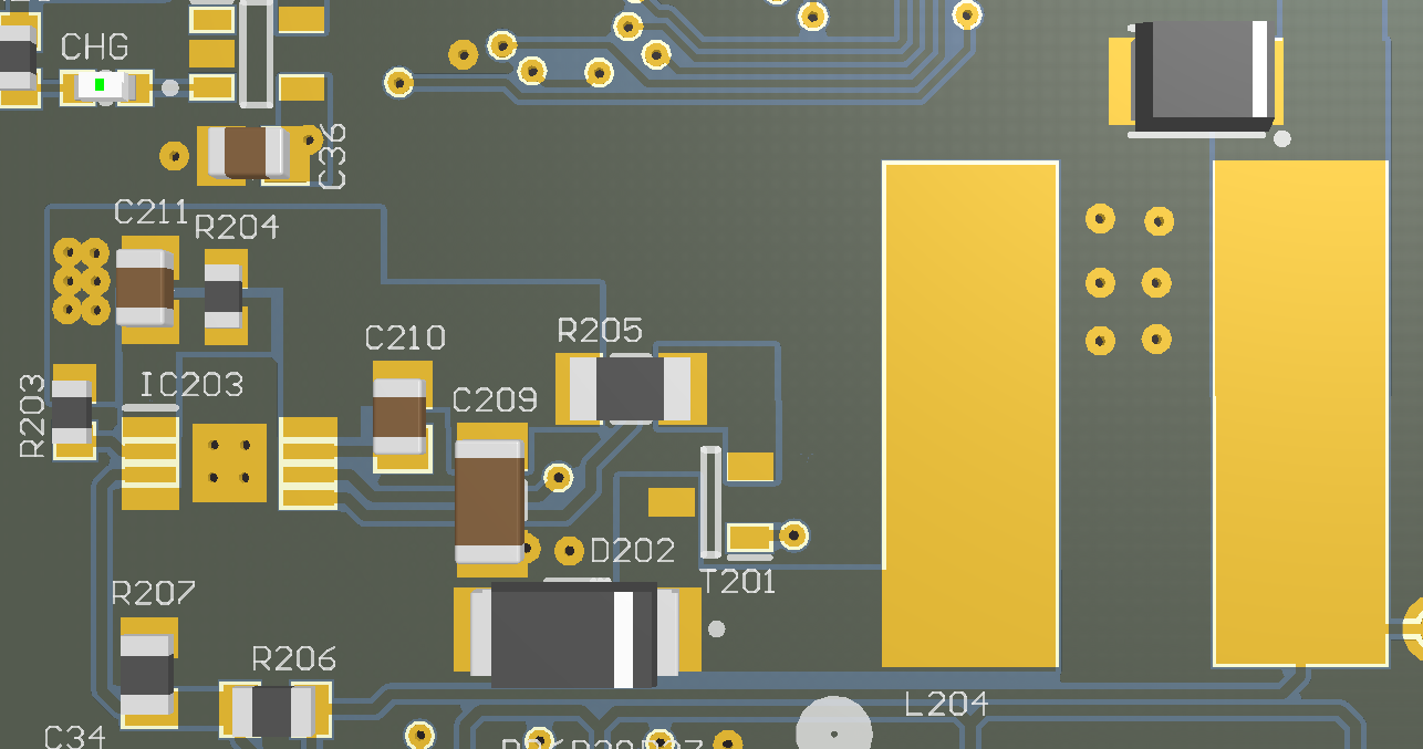
This is the PCB part that implement LM5085 buck controller:

I have strange problem with LM5085 buck Vout:

1) Vout = Vin if Vin < 7V (more or less);

2) Vout = 7V (controlled and stable) if  7V < Vin < 24V (!!!!)

3) Vout increase "linearly" with Vin if Vin > 24 (...with Vin = 32....Vout = 14, Vin = 48...Vout = 24 and so on...).

I try to increase Cin 1uF to 10uF lo ESR = same behavior;

I try to change D201 (ES2DA, B340A-13-F) = same behavior;

I try to change SHUNT resistor and Radj = no results;

I try to recalculate all the circuit at lower switching freq with webench. I rebuild the circuit with the new components...and...same result..!!!

HELP!!!

Thanks.

  • Hello Stefano,

    Have you confirmed the 7V is stable when Vin is increased? What is the the pat number of C213?

    Looks like C209 is placed in a position that is acceptable, however, the device will benefit from a bypass cap from its Vin to Gnd (100nF)?

    Hope this helps?

    David.

  • Hi David,

    Yes, the output voltage is regulated using Vin from 7V to 24V (more or less).

    When the out voltage is stable (7Vdc regulated) you can see LM5085 driving MOSFET gate. Over 24V MOS is always ON, no switching on inductor. The voltage across the feedback resistors goest to 2...2.5...3Vrms but LM5085 seems frozen.

    If I directly supply Vin = 48V (nominal battery voltage) LM5085 not drive MOSFET.

    The C213 in the PCB is in red-circle. Now I'm using EEEFC1E330P.

    Thx,

  • When you say the MOSFET is always on, I am assuming that the Vout goes to Vin under this condition? And by always on you mean that Vgate is floating below Vin by ~7V?

    Looking at your design, looks like you do have excessive ripple injected onto the FB node, becuse the ESR looks very large (1ohm). Suggest placing another bulk Cout cap in parallel and also removing C212, the additional Cout will reduce the ESR by a half.

    I do not have an explanation as to why this would happen??

    If VFB goes above the Vref, the FET should turn off, not ON and should remain off until VFB = VREF. Please look for some obvious mis connections on your board and ensure you have the right components installed.

    If you still have issues, we may need to look at the layout.?

    Hope this helps?

    David.
  • Hi David.
    I've resolved my issue.
    I tried many configuration and the problem wasn't pcb layout, capacitors or other strange things. The problem was PMOS...SI2337DS during design seems to was perfect but in fact, when I tried other PMOS, my circuit start to work in a "deterministic" manner. Now, I have change SOT-23 with DPACK Infineon PMOS and all work like a charm.
    Best regards,