This thread has been locked.

If you have a related question, please click the "Ask a related question" button in the top right corner. The newly created question will be automatically linked to this question.

LM53603-Q1: Efficiency data and transition point from PWM to PFM.

Genius 4680 points
Part Number: LM53603-Q1
Other Parts Discussed in Thread: LM53603

Our customer consider to use LM53603-Q1.

Please advise us following questions.

1. Please send us efficiency data at following conditons if you have.

Ta:-40 degree C,125 degree C

Vin:12V

Vout:5V

mode:Auto mode

2.Please let us know equation of transition point of this part from PWM to PFM.

  • Hi Kura,

    1. I have attached the closest data that I have to the requested conditions.  I have attached data for 5Vout @ -40C and 13.5Vin, and 5Vout @ 105C and 12Vin.  The efficiency should not vary greatly between these values and -40C/12Vin, and 125C/12Vin.

    LM53603.docx

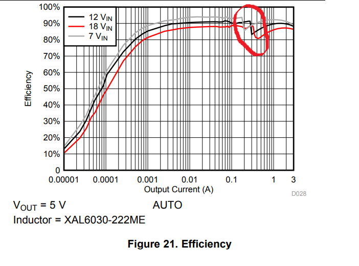
    2. Internally when the comp voltage falls to predetermined value , the device enters PFM mode and vice versa . The transition can easily seen on the Efficiency plot in Auto mode:

    Also, the load current (for a given Vin) at which the mode will change can be found in Figure 24 in the datasheet.

    Best Regards,

    Katelyn Wiggenhorn

  • Katelyn-san

    Thank you for your reply.

    we have additional question about no2.

    2.We understand Mode change depends on Output current and Vin.

      Does Mode change depend on Inductor value ?

  • Hello,

    Yes, you bring up a good point. Since the LM53603 is a current mode control device, the inductor current will directly control the transition from PWM to PFM. When the inductor valley current reaches 0A, the device will transition from PWM to PFM operation. The inductor ripple current depends on the inductor value along with Vin, Vout, and Fsw.

    Please feel free to let me know if anything remains unclear.

    Best Regards,
    Katelyn
  • Katelyn-san

    Thank you for your support.

    I calucurate IOUT of transition point using with below equations.

    Please check following.

    VIN:12V

    Vout:5V

    fsw:2.1MHz

    L:2.2uH

    In this case,If IValley = 0,IOUT=315mA

    I would like to know the reason why DN of Figure 24 Load Current for Mode change (@12V conditon) is 0.15A.

    Please advise us.

    regards,

  • Hello,

    You are correct with your calculation. This is approximately the level we would expect the device to transition from PFM to PWM when the load is increasing. This matches the 'UP' line more closely, and the efficiency figure.

    The device's COMP voltage is being compared to the peak current * Gain factor (V/A). There is a set value of COMP where the device will transition from PFM to PWM. There is hysteresis between the COMP transition point when the load is increasing or decreasing. The hysteresis is what you see in Figure 24 (150mA). The hysteresis prevents the device from transitioning back and forth between PFM and PWM modes where there is only a small transition in the load current.

    This Application Report provides a good explanation of a similar transition out of Eco-Mode: www.ti.com/.../slva388.pdf. Although this report does not cover LM53603, this provides additional information about current mode control mode devices transition in to or out of low power mode.

    Best Regards,
    Katelyn Wiggenhorn
  • Katelyn-san

    Thank you for your support.

    I used  that frequency value is 2.1Mhz in calculation.

    So I think  that caluculated value is DN.

    If you have detail block diagram of this part  to explain PFM/PWM transition point ,please send it to us.

    Regards,

  • Hello,

    I do not have a block diagram of this part to explain the PFM/PWM point. You can reference the applications note to understand the transition from light load mode to PWM in current mode control converters.

    Please let me know if you have any further questions.

    Best Regards,
    Katelyn