Hello,
I am measuring the output voltage through a little sample of the it (voltage divider), and then a isolated Oamp is connected. I would like to know if what I am doing is right:
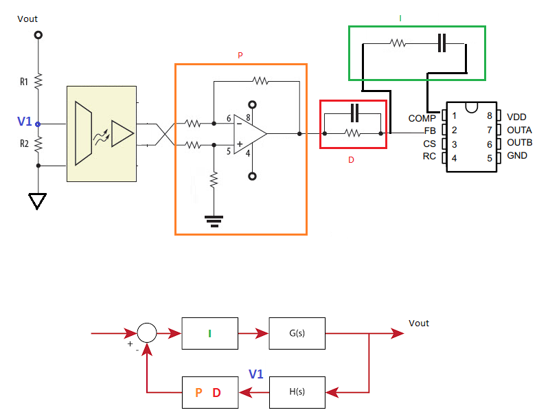
The UCC3808A-2 has particularly 2 pins to place the compesation network: FB (Inverting input to the error amplifier) and Comp (Output of the error amplifier and the input of the PWM comparator).
The proportional component of the controller is implemented through a Oamp after the Isolated Oamp (this last has unitary gain). Then I have placed the derivative element, which is achieved with a RC in parallel, and it is connected to the FB pin; the integral component of the compensator is placed between FB and COMP as a RC series network (see Figure).
1. Is the PID well implemented?
2. Does the block diagram in the figure represent the previous mentioned configuration?
Thank you for your help.
Best regards,
David