This thread has been locked.

If you have a related question, please click the "Ask a related question" button in the top right corner. The newly created question will be automatically linked to this question.

PMP9256: Output Ripple is too high

Part Number: PMP9256

Hi,

This reference design was assembled and tested physically at Vin = 24Vdc, with a DC electronic load (CSI3711A).

The load was set to draw a constant current of 5A.

Test procedure:

1. Turned on Vin=24Vdc from a bench power supply to PMP5296

2. I see Vout=12Vdc + approx 600 mVp2p at no load

3. Turned on the load to 5A

4. I see about 4.21 Vdcp2p !! (attached picture)

According to the waveforms found in TI's test report for this design, the ripples should not exceed 200mVp2p under these conditions (24Vin and 5A load).

Could you please elaborate on your test conditions? What type of load was used during TI's testing?

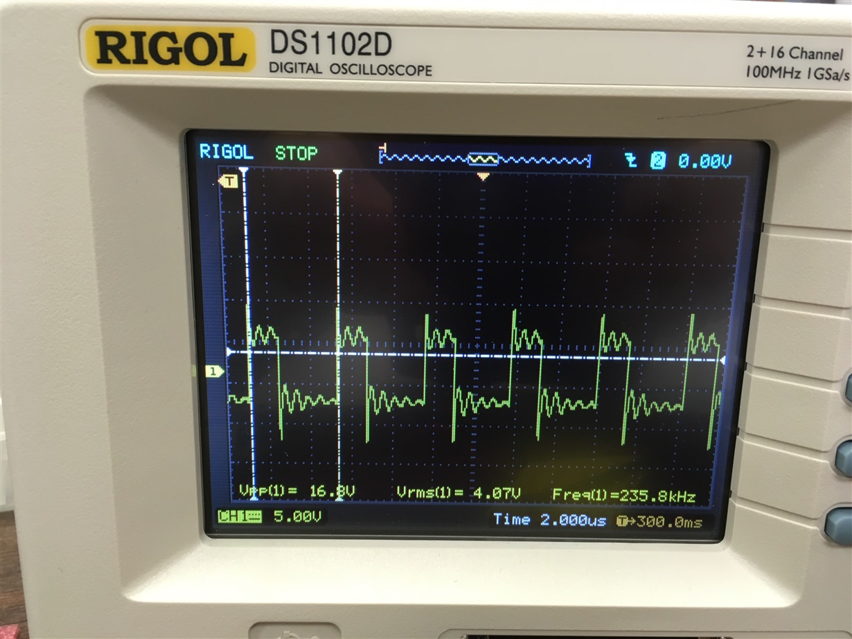
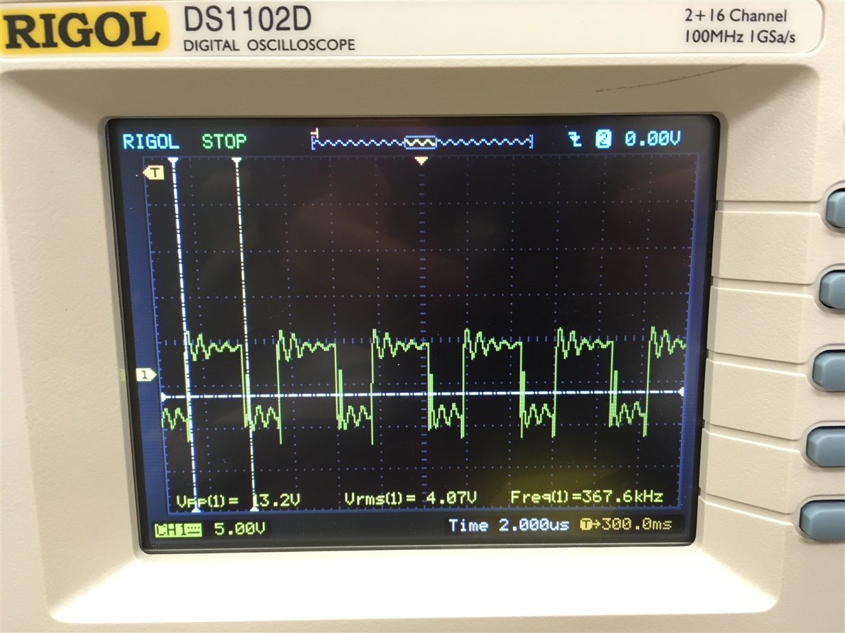
Attached are also the switching waveforms, primary and secondary, at a 5A load for your reference.

Thanks for your help,

Isabelle


  • Hello Isabelle,

    For the output ripple measurement, I suspect that you are using a flying ground lead. Try using the tip and barrel technique shown in item 9 here, which was done for the test report measurement:

    https://training.ti.com/psds-common-mistakes-dcdc

    Since the flyback has pulsating current in the output capacitor, there will always be switching spikes on the output voltage. You may need an additional output filter.

    Your switch waveforms show a lot of ringing, which could indicate common-mode current in the measurement. Check to see that the input to output bridging capacitor is installed right across the transformer. As a test, short the input ground to output ground very close on the board to see if the ringing changes or goes away. If so, check the placement and effectiveness of the bridging capacitor.

    Regards,

    Bob Sheehan 


  • Thank you Bob for your help.

    However the link you sent is broken.

    I will get back to you after checking on the bridging cap.

    If it doesn't help, I will try adding a basic low-pass RC filter on the output.

    Isabelle

  • Hello Isabelle,

    Sorry about the link, I will have to see if there is any reason you cannot access it. From the presentation on measuring output ripple:

    So on this one, we've got two output voltage measurements. On this left one, there's a lot of noise, and it's very dirty. It's very ugly-- this output voltage measurement. And on the right, it's much cleaner, and the output voltage ripple is very visible. So which a voltage measurement is right?

    So what happened and what's causing such a noisy measurement on the first one is measuring the switching node-- there's a couple of things actually. First, we're measuring the switching node at the same time as the output voltage ripple, and what this causes is coupling through the oscilloscope back from channel 2, which is the switching node, back to channel 1.

    The other thing with this measurement is no bandwidth limiting is used. This causes you to pick a very high frequency noise, which may really not be there. Typically, when you're measuring the output voltage ripple, you're more concerned about the conducted noise and not the radiated noise. The noise at these high frequencies typically will not propagate down the PCB due to the parasitics of the PCB.

    So the best way to take a measurement is to use bandwidth limiting and remove the switch node probe. This gives a very clean switch node output voltage ripple measurement, and it looks more like what you would expect. So there are some cases where you may want to do a high bandwidth measurement, but in those cases, you just be careful to know that you're measuring what you really want to measure.

    So just a few more tips when you're measuring the output voltage ripple-- so first, it's good to measure right across the output capacitor. And when you measure it, you should use a tip and barrel approach as shown in this middle image-- tip and barrel so that the probe is right across the upper capacitor, and there's a wire wrapped around the ground of the probe that's connected to the ground side of the probe.

    Another thing you can do is use probe sockets, and then you can just plug it in and get a really good measurement. One thing you definitely don't want to do is have a flying ground lead like the image on the right. This just creates a loop that can pick up a ton of noise and cause a lot of inaccuracy in the measurements.

    Another couple of things with a setup-- as we said before, it's good to limit the bandwidth to 20 megahertz just to make sure you're picking up the noise that you really want to measure. You want to use the full y-axis scale, so use the smallest voltage scale possible just to include-- get the best resolution out of the oscilloscope.

    Lastly, if you're measuring a very low output voltage ripple, consider using a one-to-one probe or an active probe. This helps to limit the noise in the measurement, again, to get a more accurate measurement

    Regards,

    Bob Sheehan

  •  Hi Bob,

    The tip and barrel technique improved the ripple seen to about 600 mV, which isn't too bad compared to TI's reference test report.

    Attached is a screenshot of the new waveforms: primary and secondary switching, and output ripple.

    The ringing seen on the secondary switching waveform seem to have gone away after upgrading a transistor. The ringing on the primary side remains (CH4). We are still investigating why that is.

    Also the by-pass caps are layed out exactly like in the reference design, and shorting them did not make any difference.

    Thank you for your help!

  • Thanks for your help Bob. The ringing and ripples we see are acceptable now.

    Isabelle