This thread has been locked.
If you have a related question, please click the "Ask a related question" button in the top right corner. The newly created question will be automatically linked to this question.
Hello Team,
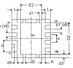
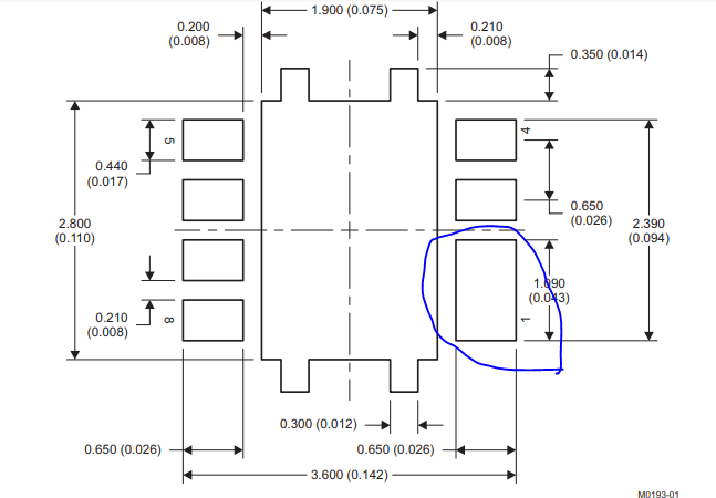
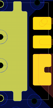
I have noticed that the CSD87335Q3D datasheet on the Stencil recommendation in section 11.3 recommends a single aperture for the pin 1-2.
On the other hand, in Figure 34, is shown that the pads for pin 1-2 are separated.
Can you recommend how the solder mask should be considering that the stencil has a single aperture and the pads are two?
It looks as a mismatch between the Figure and Stencil.
Thanks,
SunSet
Hello Brett,
Figure 4 shows pads which are not connected while the stencil show a "single pad" .
This is what I find misleading.
SunSet
Sunset,
I am not seeing what you are seeing.
The top on the front page says they are connected:
Figure 4 on the datasheet is actually a curve and there is not Figure 34 as you state above:
The mechanical drawing on page 18 shows that the pins are clearly attached (again via the d4 dimension):
And finally, the recommended stencil shows that because these pins are attached, you can treat them as one pin when you solder:
These are the only relevant pictures I see in the datasheet. What image is the source of your confusion?