This thread has been locked.

If you have a related question, please click the "Ask a related question" button in the top right corner. The newly created question will be automatically linked to this question.

TL7700: Could you tell me about TL7700?

Part Number: TL7700
Other Parts Discussed in Thread: TPS3700

I posted it at the end of the following thread, but I also set up another thread just in case.

https://e2e.ti.com/support/power_management/supervisor_reset_ic/f/886/p/667726/2477836#2477836

Will you teach me?

-----------------------------------------------------------------------------------------------------------------------------------------------------------

Thank you for your response.

I am working with "Bob Lee 62837", he is an engineer and I do customer's Q&A support.

I talked with the customer about this matter and the situation was as follows.

The slew rate of the RESET signal doesn't fluctuate with CT capacity, but in the past there were the following answers.
(We and the customer don’t discuss this answer because we can not confirm who sent this answer in the past.)


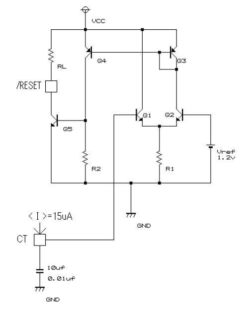
The figure above is a composite of the TL7700's internal and peripheral circuits.
① The comparator output of Q1 and Q2 becomes the current of Q4.
② To make the current of Q4 zero, it is necessary to set the collector current of Q2 to zero.
③ This assumes that the comparators Q1 and Q2 become Q1: ON, Q2: OFF, but a voltage difference of about 50 mV is required for Q1 and Q2.
④ Therefore, if slew rate of CT is loose, it takes time until this voltage difference occurs, during which Q5 also turns ON and the slew rate of RESET signal becomes loose.

Is this consider correct?

if this consider is correct, does the slew rate of RESET signal depends on CT capacity?

Best regards,
Masumi Sekiguchi

  • Hi Pokkun,

    where do you have this schematic from? Is it really the internal circuitry of TL7700? I don't think so.

    You say, that the slew rate of rise time depends on CT capacitance? Could you show us scope plots which shows this?

    Kai
  • Thank you for the reply.
    The person who presented this material have confirmed, but is unknown.
    I'm sorry.

    > You say, that slew rate of rise time depends on CT capacitance?
    > Could you show us scope plots which shows this?

    ⇒ I searched for equivalent materials.
    I attach it and send it.

    <Additional question>
    If the reason is right, I think falling time also will vary depending on Ct.
    Can you presentation the results verified in the same way?

    TL7700.pdf

    Best regards,

    Masumi Sekiguchi

  • Hi Pokkun,

    nice measurements! I'm surprised to see this!

    Kai
  • Masumi,

    I replied on your other E2E post but I will post the same response here too. I can't confirm the internal schematic you provided since I have not seen this before and it does not match what is provided in the datasheet. Since TL7700 is an open-collector output topology, a capacitor on the /RESET output so only affect the slew rate when /RESET signal is "low" and going "high" since the capacitor on the output will need to charge thus slowing down the slew rate of the output signal. But when the /RESET output is "high" and goes "low", the capacitor will be shorted out and thus has no effect. Please let me know if this agrees with your thinking. Thanks!

    -Michael
  • Hi Michael,

    CT does not seem to be connected to the /RESET output.

    Kai
  • Kai,

    Understood. I am referring to actually placing an external capacitor from /RESET to GND to change the slew rate of /RESET when rising. This is not referring to the reset delay which comes from the CT pin. See the attached powerpoint for adding /RESET slew rate to voltage detectors. I believe the same tests we did for TPS3700 will also apply for TL7700 since they have open-drain/open-collector output configurations.

    -Michael

    /cfs-file/__key/communityserver-discussions-components-files/196/5635.Adding-programmable-delay-to-Detectors.pptx

  • Michael-san, thank you for contacting me.

    Do you understand my question?

    You are arguing that the slope will change with a capacitor that perhaps connects to the / RESET output.

    I am discussing why the slope changes with a capacitor connected to the CT pin.

    There is also the result that the capacitance of the CT pin presented in the past and the slope of / RESET change.

    2021.TL7700.pdf

    Looking at the result, the slope of the rising edge of / RESET becomes gentle as the capacitance of the CT pin increases.

    If you convert the graph on the last page of the document attached in PDF to the linear scale on the horizontal axis, it becomes the figure below.


    Looking at this, the capacitance of the CT pin and the slope of / RESET appear to be proportional.

    I think that this is a reasonable result even from the circuit diagram below.


    Is my understanding correct?

    If it is correct ....

    Q:Could you tell me the correct formula for CT pin capacitance and slope of / RESET under the following circuit conditions?

    ※Both the rising edge and the falling edge.

    Best regards,

    Masumi Sekigucih

  • Masumi,

    I understand your question now. The only information we provide related to the CT pin and delay is the current source current which is 15uA typical. The actual equation depends on the current source current, and the voltage threshold that the cap charges to. But the datasheet provides an estimation in section 8.3.3

    delay = Ct x 10^5 seconds where Ct is the capacitance in farads

    Please also refer to Figure 6 in the datasheet which shows the delay vs timing capacitor.

    Let me know if you have any more questions. Thanks!

    -Michael

  • Michael-san, thank you for contacting me.

    Q:If the calculation formula can not be presented,

      will the CT V.S. Rise (Fall) Time inclination tell me how far it will be inclined under the worst condition?

     ・It’s OK theoretically value.

    Best regards,

    Masumi Sekiguchi

  • Masumi-san,

    The equation and figure only provide typical estimation. The tolerance of the capacitor will also affect the delay.

    -Michael
  • Thank you for contacting me.

    I and the customer know that the tolerance of the capacitor is affected.
    On considering that, the customer is wanting to know equation according to typical estimation.
  • Hi Masumi,

    Where did that schematic come from?

    The way the circuit works is the capacitor charges to a reference voltage at a constant current so by changing the capacitor you can change the delay. It follows the capacitor equation
    I = C dv/dt where dt is the delay. Solving for the delay

    Delay = Capacitance * Vref / charge current

    For the TL7700 the approximate delay is:

    delay in seconds = Capacitance in F * 10^5


    The delay has a range that gets wider depending on capacitor tolerance.


    -Michael
  • Where did that schematic come from?

    ⇒I have be sent them from customers, so I also don’t know the document identity.

    We know about delay, because it is clearly shown in the datasheet.

    "Rise (Fall) Time" we want to know refers to slew rate.

    I also know that it is not described in the data sheet for this description, and then I think that past results are not left.

    However, customers are in trouble.

    For that,

    ①: Since it is also a theoretical calculation formula, please tell me how to calculate dependency of "CT V.S. Rise (Fall) Slew Rate".

    ②: If "①" cann't be done, please tell me how many worst hours of slew rate should be estimated.

    Best regards,

    Masumi Sekiguchi

  • What is the situation?

    Please tell me the formula or the worst value.

    Best regards,
    Masumi Sekiguchi
  • Masumi,

    1. The equation I posted above defines the reset delay, not the slew rate. The slew rate doesn't change unless you have a capacitor from /RESET to GND at the output then the slew rate changes according to the capacitor value.

    2. We do not provide worst values. We only provide typical estimation for this device.

    The delay = the capacitor in Farads * 10^5

    Please see figure 6 for approximation of reset delay.

    -Michael

  • Thank you for your answer!

    I am Takahiro Nishizawa.
    I am involved in business with Masumi.

    Could you tell us the variation of slew rate in rise and fall?
    We don't need guaranteed value.
    I want to know reference value about variation of slew rate.
    For example, ±--% or --mS and so on.

    Best regards,


    takahiro Nishizawa
  • Takahiro,

    The only thing we can guarantee are the specs in the datasheet. Table 6.6 Switching Characteristics states the max value for the slew rate as 15us. Because this is so small compared to the reset delay of 1ms, the 15us slew rate should not have much effect.

    Can you provide details why the slew rate information is needed for your application? This can help us add the important specs for future datasheets. Thanks!

    -Michael