This thread has been locked.

If you have a related question, please click the "Ask a related question" button in the top right corner. The newly created question will be automatically linked to this question.

TLV755P: IC MARKING CODE MISSING FOR DEVICE PTLV75528PDBVR

Part Number: TLV755P


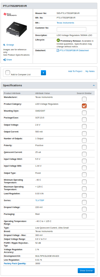
PLEASE PROVIDE ME IC MARKING CODE, FOR IC PART NO. PTLV75528PDBVR.

  • Hi Aswath,

    The PTLV75528PDBVR does not have a marking code yet as it is a pre production device meant only for prototyping and evaluating a device. The marking code will be included once the part is fully released to the web.

    Regards,
    Mark
  • Hi Mark,

    As the generic data sheet TLV755P specifies that the product is available in Fixed Output Voltages range i.e 0.6 - 5 volts.

    I got samples of PTLV75528PDBVR which has fixed output of 2.8 V. Please find the image attached as reference.

    As per out Test-Setup and circuit diagram, we are getting maximum output of 2.6 V.

    When the input voltage is above 4.5 volts, the IC gets heated too much.

    Please find the test circuit and the readings recorded.

    Waiting for your reply.

    Warm Regards,

    Abhishek / Aswath

    READING.xlsx4452.CIRCUIT DIAGRAM.pdf

  • Hi Abhishek / Aswath,

    When the input voltage reaches 4.5V it is possible that the LDO will go into thermal shutdown depending on the load current.

    Based on the table you sent it looks like there could be a measurement issue. There seems to be a large votlage drop across the multi-meter, could this be causing the output voltage to be measured incorrectly? There also seems to be a discrepancy between the measure output current and voltage and the calculated current using the output voltage and load resistor. The LDO appears to have a constant output at 2.5 or 2.6 depending on the load current until the input drops low enough to where the LDO would be in dropout. This suggests that the LDO is actually regulating the output voltage. Would you be able to provide a scope shot showing the input voltage, output voltage, and output current measured at the pins of the LDO? This would be very helpful in debugging.

    Best Regards,
    Mark
  • Hi Mark,

    I have attached the snapshot of scope with No-Load & With-Load (10ohm, 5W) current 240 mA.

    legends: 1- Outpput

    2- Input

    Image1 - No-Load

    image2- with load

    I am not getting 2.8 volts as output across the load.

  • Hi Abhishek / Aswath,

    Do you still have the multimeter connected when you took the second measurement? It would be normal to have a drop on the order of 15mV as you scale the load to 250mA, but 200mV seems really high. Are you testing the LDO on an EVM? There is a universal EVM you can use to evaluate the LDO www.ti.com/.../MULTIPKGLDOEVM-823

    I will also order samples and see if I can get similar results to you.

    Regards,
    Mark
  • Hello Mark,

    Thanks for looking into the issue so closely.

    No i did not connect any multimeter while taking the DSO readings.

    yes this what our concern is, I have seen LDO's to drop in order of few mV, but this one is acting weired.

    We have designed our own board for that. Right now we can not have any EVM.

    I would appreciate the effort put by you to resolve this issue.

    Thanks & regards

    Abhishek

  • Hi Abhishek,

    I should get parts later today or tomorrow for the 2.8V version of the PTLV75528PDBV, i tested a 2.5V version of the part I have here and it did not display the same behavior as what you are showing. With a 500mA load I was only seeing 40mV of drop due to load regulation. Would you be able to send me a picture of your test setup while I am waiting on these parts to arrive?

    Regards,
    Mark
  • Hi Mark,
    I got 2.8 V , It was because of measurement errors,
    The measurement was effected due to parasitic element.
    Thanks a lot for helping all the way.
    Best Regards,
    Abhishek
    +91 78480 43044