This thread has been locked.

If you have a related question, please click the "Ask a related question" button in the top right corner. The newly created question will be automatically linked to this question.

LM2575: whenever load draws current more than 1 A, IC does not restrict it.

Part Number: LM2575
Other Parts Discussed in Thread: LM324

Hello Sir,

              I have used all components as specified in datasheet only. I have used R1, R2 values,which are derived from Formula as mentioned in data sheet.

Input voltage range: 22V-30VDC

Output voltage=21V

Output current=1A

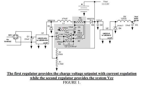
 Load for the circuit is battery. I am using circuit as battery charger.

I am getting desired output voltage of 21V. It is clearly mentioned in data sheet of IC that its of 1A.

The problem I am facing is that whenever load draws current more than 1 A, IC does not restrict it. Current supplied by IC goes upto 3A, after which IC Heats up and goes into thermal shutdown. After which output of IC goes to 0V.

Please help to resolve.

Dushyant

  • There are several things that might be going on:


    1. We would like to see your schematic and a snapshot of your layout

    2. A Vin of 22V and Vout of 21V may not be possible.

    3. The LM2575 is not meant to be a current regulator and is not suitable for charging a battery without extra circuitry.

    4. The current limit of this device can by as high as 3A to 4A; this is where the current will be limited.

    5. The inductor must be rated for this current.

    6. At high input and a shorted output, the device may be heating so fast that the TSD may not protect it form damage.

    7. You may want to look on the TI website for battery charging solutions that would better fit your application.

  • Hello Frank De Stasi,

    please see my below comment:

    1. We would like to see your schematic and a snapshot of your layout.- it is same as data sheet.

    2. A Vin of 22V and Vout of 21V may not be possible. -In put Voltage is =24V and from data sheet it 21V output is possible, please confirm.

    3. The LM2575 is not meant to be a current regulator and is not suitable for charging a battery without extra circuitry.- I want LM2575 to provide 21V 1A to load. What extra circuitary will I require? Please mention.

    4. The current limit of this device can be as high as 3A to 4A; this is where the current will be limited. -Datasheet mentions it is 1A Regulator. So how come is Continuous current limit 3A or 4A? Datasheet does not mention it anywhere.

    5. The inductor must be rated for this current.- Yes inductor is rated for load current

    6. At high input and a shorted output, the device may be heating so fast that the TSD may not protect it from damage.

    7. You may want to look battery charging solutions that would better fit your application.-please suggest if you have any solutions.


  • Hello ,

    I have refer attached document and implemented the below circuit with following changes, suitable for my application.

    As my application did not require current greater than 1Ampere, the suitable inductor value (L1) was 330uH.

    I need to limit the current below 1 Ampere. So I changed R5 to 0.47E. As per calculations, current limit should be at about 400mA.

    I have used LM324 as OpAmp IC (U3). Input voltage is 24VDC.

    When I connected the battery, the current was restricted to 400mA. But I observed that, the temperature of IC rose upto 75 degree, after which it was stable. Package of IC LM2575 is TO220, IC is used without heatsink and circuit is in open air.

    As the current is restricted at 400mA, I am unable to figure out the reason for such high temperature rise. On the field, the circuit will be enclosed in box and ambient temperature would rise to 50 Degree Celsius. In such circumstances, it wont be possible to use the IC with such high temperature rise.

    Please inform what could have gone wrong? 

    buck converter provides battery charger and system power.pdf