This thread has been locked.

If you have a related question, please click the "Ask a related question" button in the top right corner. The newly created question will be automatically linked to this question.

TPS61163A: Unique Usage to Realize Flashing

Part Number: TPS61163A
Other Parts Discussed in Thread: LM36274

Dear, Sir.

My customer is considering to realize 1 to 2 seconds flashing applying TPS61193A.

The flashing will be executed after TPS61193A start-up.

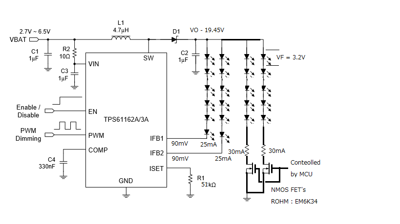
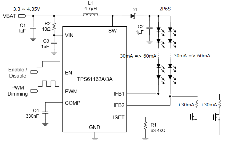
VIN condition & brief configuration is as below.

Maybe, enough headroom voltage must be maintained.

They would put the additional resistor & NMOSFET to be prepared addition 30mA paths.

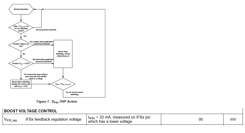
TPS61193A has unused pin function to connect IFBx to GND, so I am confusing now.

Please give your advice,

This kind of usage is possible or not?

Is there any concern & bottle-neck under this kind of usage?

Best Regards,

H. Sakai

  • Hi Sakai-san,
    May I know what is the sequence of enable, flash PWM, and gate signal of mosfets connected to IFBx?
    unused IFBx connected to gnd is for unsued pin detection. so the sequence is critical.
    Besides, connection as you illustrated cannot gurantee extra 30mA, there is no current regulation for these extra 30mA.
    Can you share with us , what is the LED configure, and what end equipment is requireing this application?
  • Dear, Caryss-san. 

    Thank you so much for your reply and sorry for my poor explanation. 

    Application is Smartphone. VIN source will be Battery pack, 3.3 ~ 4.35V. 

    LED configuration is 2 parallel, 6 series. These current are all controlled by TPS61163A. 

    Normally, operating under , ISET = 30mA sink current, EN = HIGH and PWM = 100% duty

    on TPS61163A . 

    External NMOS FET gates are driven by MCU.

    When Flashing operation was needed, external NMOS FET become ON, so extra current flows

    such as +30mA adding

    on TPS61163A sink current(30mA) through LED strings(such as total 60mA). 

    I also suppose this circuit is risky because Headroom voltage(IFBx voltage) will be 

    quite low according the datasheet.

    Under such condition, NMOS FET could not operate in saturation area so that it would

    not be expected enough current control. 

    At this time, I would like to make sure followings; 

    1. Under normal operation, How much voltage would be reasonable on Headroom 

       volage(IFBx voltage)? Around 90mV? over 0.5V? 

    2. If the Headroom voltage(IFBx voltage) went down the normal Headroom voltage

       due to external circuit influence, I wonder the protection function on TPS61163A

       never activated? 

    3. If you had  any better idea to realize the Flashing operation, Please give your advice. 

    Best Regards, 

    H. Sakai

  • Hi Sakai-san,
    Your concern about headroom voltage is right. In normal operation, the lower one of these two IFBx is regulated to 90mV, so this is too low for NMOSFET. As in your application, I would suggest use LM36274, which is 4 channels of 30mA, supporting exponential dimming, auto-frequency, high accuracy. The extra benefit is it is a backlight driver integrated LCD bias. LM36274 is designed for smartphone application, you could use 2 channels in normal operation and add the other two when flash.
    Hope this helps.
  • Dear, Caryss-san.

    Sorry again and again.

    I think one channel can be disabled if FBx pin is connected to GND.
    In addition, This device has the protection function for LED strings OPEN/SHORT.

    Could you please let me know FBx pin low side threshold to be stopped operation if there is.

    Best Regards,
    H. Sakai
  • Dear, Caryss-san. 

    Thank you so much for all of your advice. 

    I proposed 4ch LED Driver LM36274 as your suggestion. 

    They would like to reduce the total cost as well for the change. 

    At this time, I would like to make sure following solution could be realized or not. 

    1. Add 2 5LED strings ON/OFF control using NMOS FET's by MCU.

        The current is set by the resisters. Low voltage type will be used as NMOS FET(EM6K34). 

    2. I think this solution will not affect to IFBx(Headroom voltage). 

    3. I wonder there is a influence to Boost converter behavior taking this solution? 

    Best Regards, 

    H. Sakai

  • Hi Sakai-san,
    This configuration cannot regulate LED current in the extra strings controlled by MOSFET. The variation could be large. I don't recommend using like this.