


Other Parts Discussed in Thread: TIDA-01405, , TPS82130, TPS63710
Tool/software: WEBENCH® Design Tools
Dear Sir/Madam,
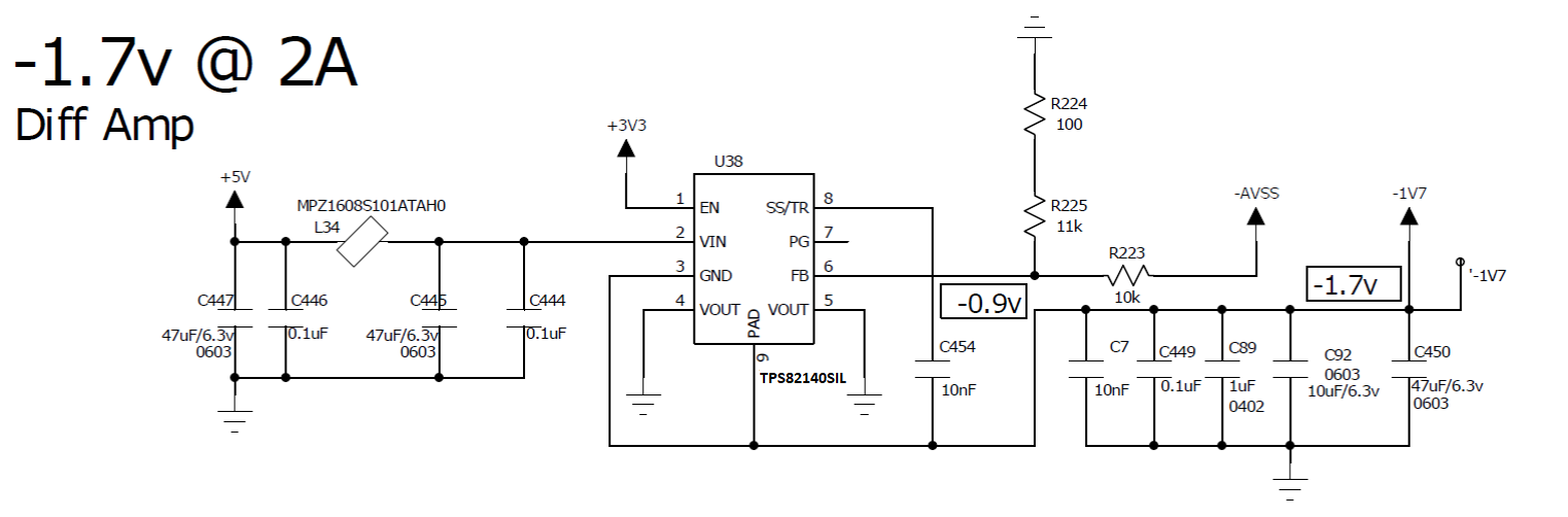
I am using TIDA-01405 Design as reference.
Part Number : TPS82140
Input = 5v
Output = -1.7v
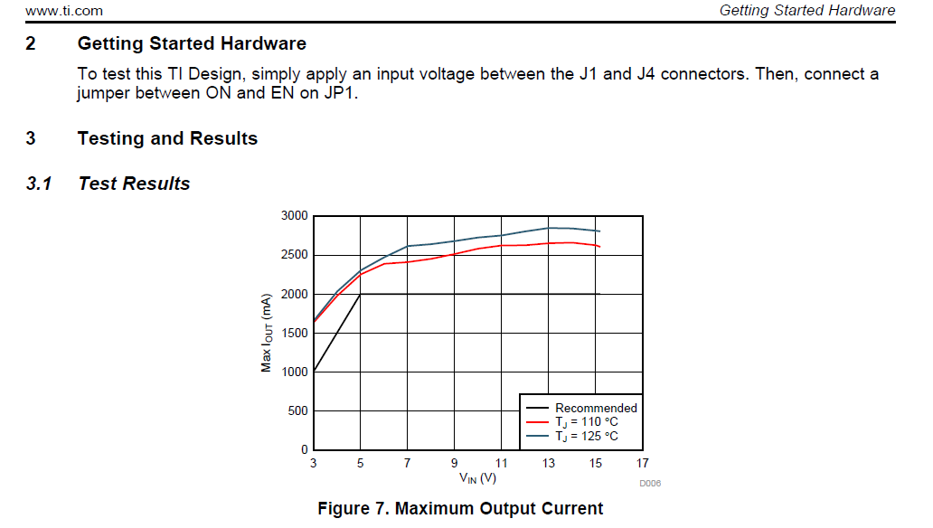
What will be the max output current at -1.7v Output?
My schematic is as below.
Best Regards,
KPK


