Other Parts Discussed in Thread: TPS54335A,
The threshold to leave skip mode is at much higher current level.
But at datasheet fig.10 shows that the level is around 50mA only.
Please directly see below scopeshots in different load conditions.
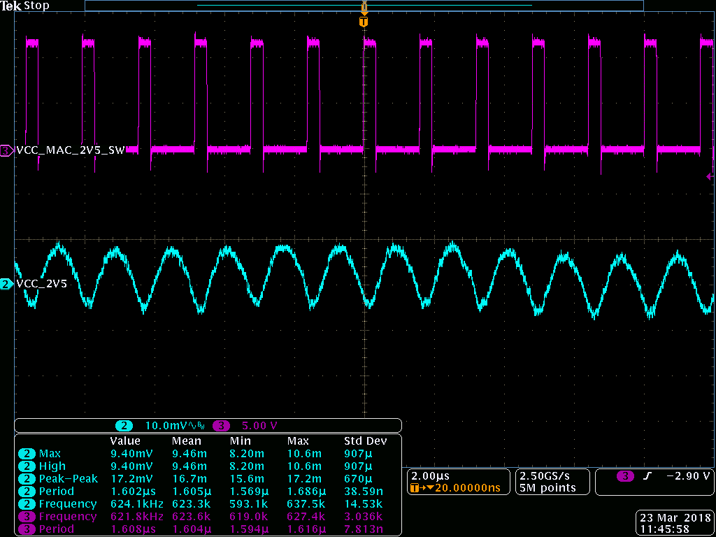
no load
100mA
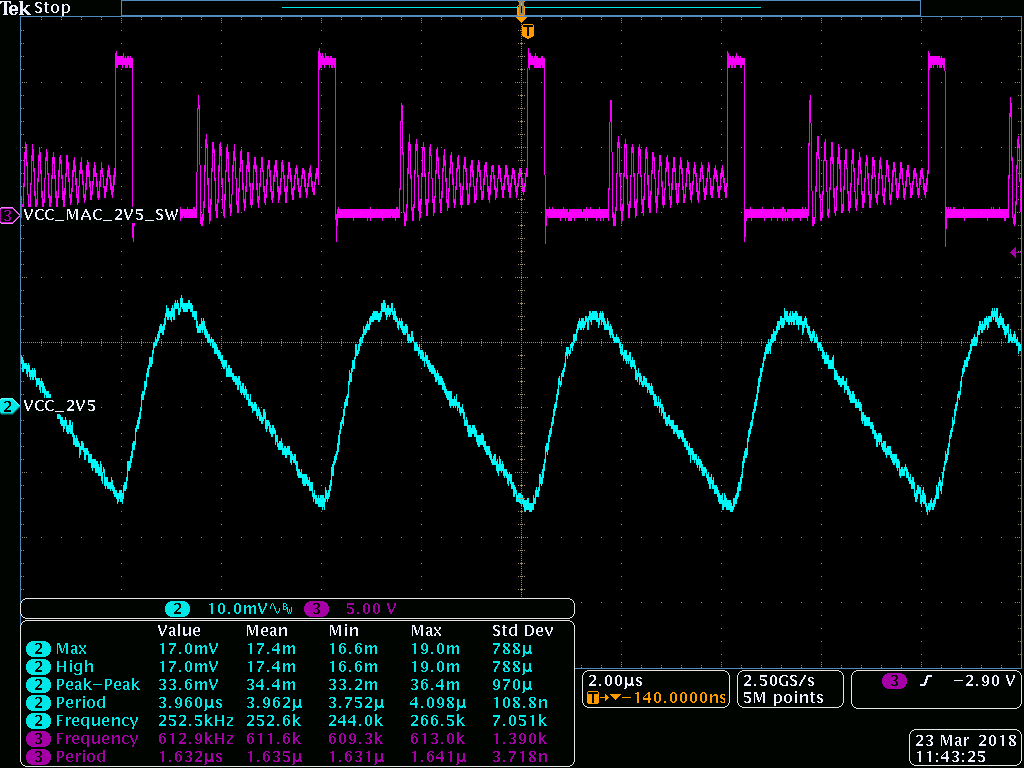
200mA
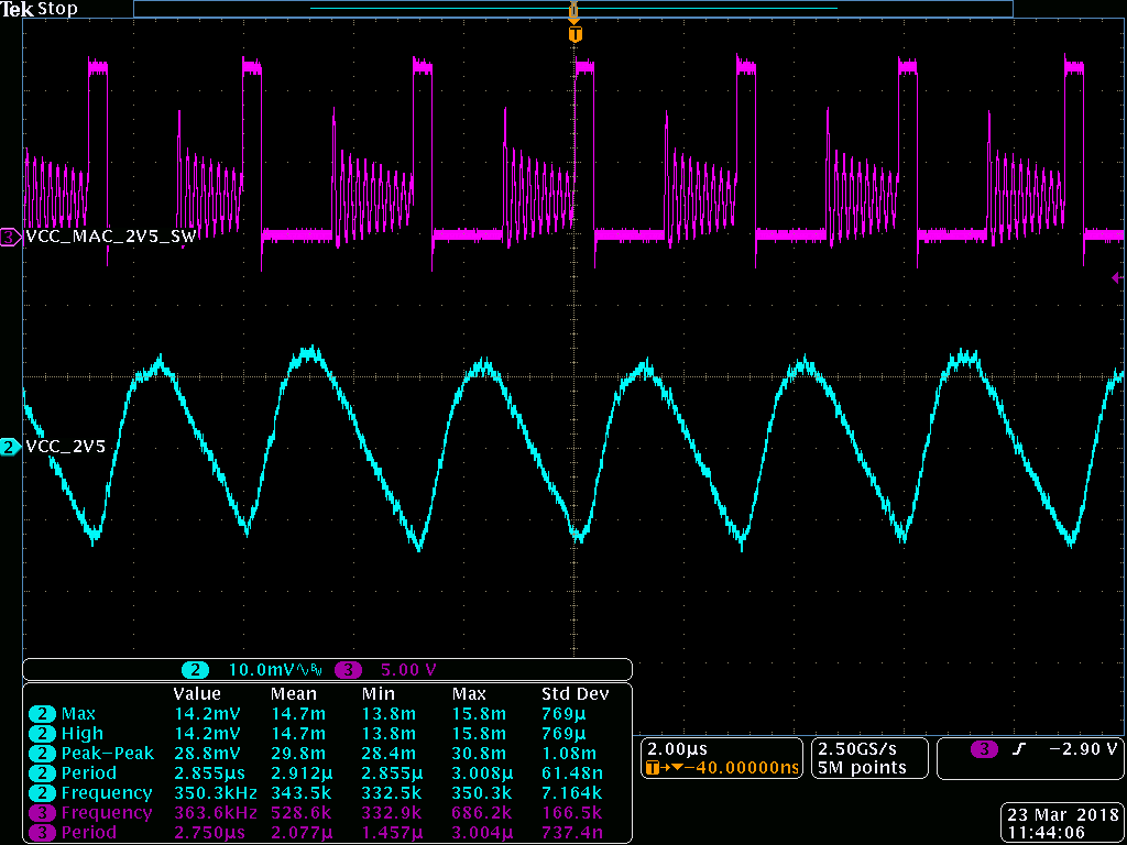
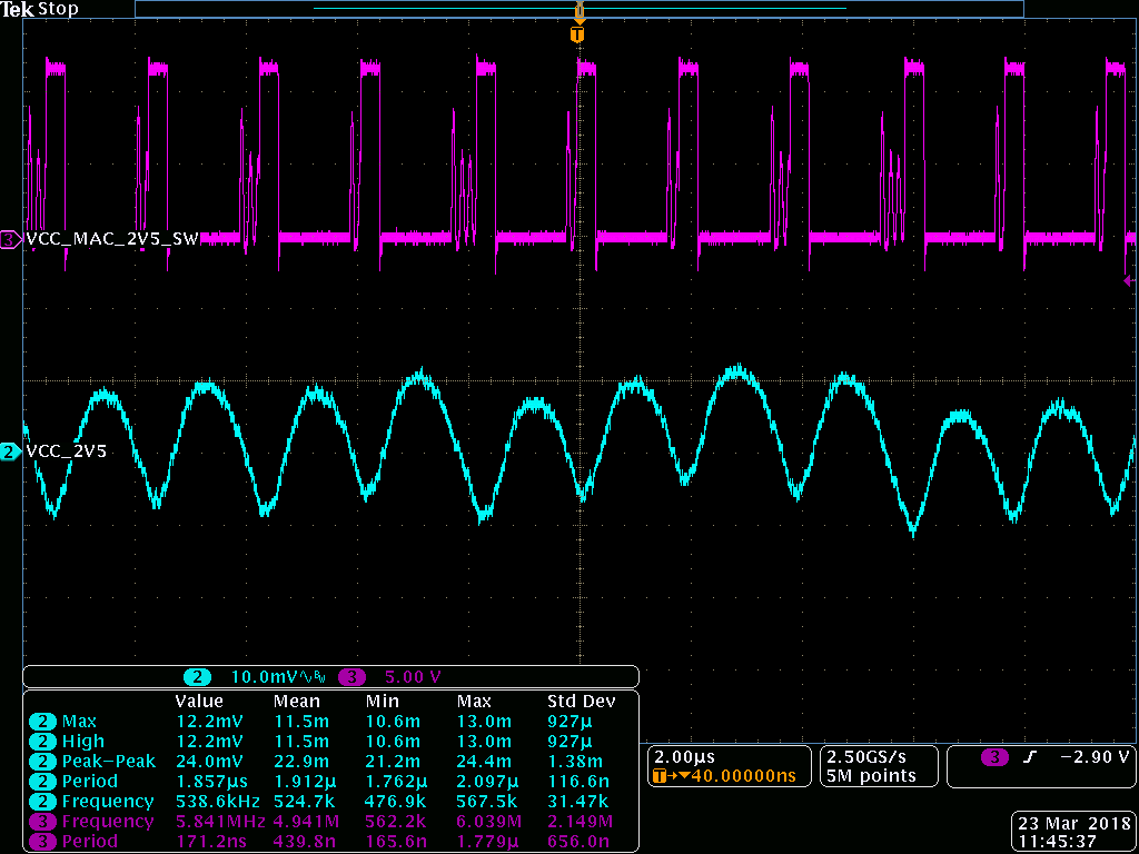
300mA

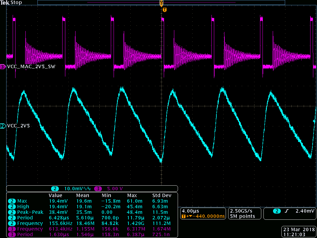
400mA
500mA