This thread has been locked.

If you have a related question, please click the "Ask a related question" button in the top right corner. The newly created question will be automatically linked to this question.

UCC28950: SLUA560C - Rectification MOSFET Loss Calculation

Part Number: UCC28950

Hi,

I am using the AppNpte SLUA560c to get into the design of a DC/DC using the UCC28950.

My question is regarding EQ. 71, which is used to calculate the losses in the active rectification MOSFETs. This part of the equation is used to estimate the switching losses


I have two question to this formula:

  • In figure 2 Q_E is switched on, when the Current I_QE is zero. From my understanding this is zero-current switching and should not produce switching loss. Why is the MOSFET Turn On Rise Time t_r included in the equation?
  • In figure 2 Q_E is switched off, when the Current I_QE has the value I_MS2. Why is instead of this current the output current (P_OUT/V_OUT) used to calculate the switching losses?

Best regards,

Torben

  • Hello Torben

    I'm afraid that you are correct - there is an error in the app note.

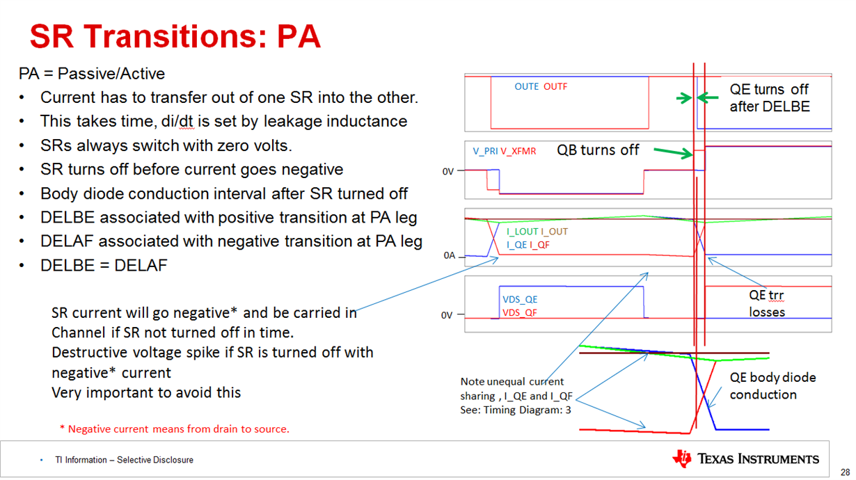
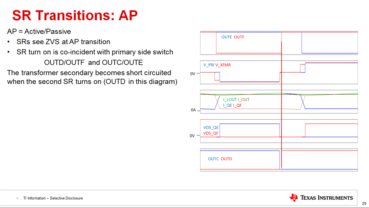
    SR Turn-on for QE and QF is lossless - it is done with zero current in the part and zero volts across it.

    SR turn-off for both QE and QF is a ZVS transition - there is no voltage across the device when it is turned on.

    There is however current in the MOSFET as it is turned off. This current then flows in the body diode until it decays to zero - this is the interval during which the transformer secondary current is transitioning out of one secondary winding and into the other. This will incur Vf*I(t) losses - (Vf is the body diode forward voltage)

    The SR switching is shown in the images below.

    Now, let's look at EQ71 - below

    The first term is simply the I^2R losses in the MOSFET

    The second (yellow) term is I think in error - The losses during the time when the current is moving out of one SR and into the other are I^2R losses as the current rises in one SR (red trace for QF below) and I^2R losses in QE until the time when QE is turned off and the losses then become Vf*i(t) until the current has decayed to zero. (blue trace for QE below). Of course the QF and QE losses will swap over during the following switching cycle.

    The red term is in error and should be ignored - as you pointed out the SRs are ZVS

    The Green term is the energy needed to charge and discharge the gate - this term is correct

    ----------------------------------------------------------------------------------------------------------------------------------------------------------------------------------------------------------

    The SRs are switched at zero voltage so that there is no loss associated with the discharge of the Coss. There are however other losses - the energy needed to charge and discharge the gate capacitance at each switching cycle and the losses associated with the body diode conduction in the interval between the drain of the MOSFET being driven down to zero volts and the MOSFET channel being turned on.

    Please let me know if you need any further information

    Regards  Colin

  • Hi Colin,

    thank you for your quick and detailed answer!

    In case you are going to correct the app note it may also be worth checking the SLUC222 UCC28950 Excel Design Tool. I think it uses the same calculations as in the app note.

    Regards Torben
  • Hi Torben
    Yes - thanks for pointing that out - these kinds of errors have a habit of propagating across multiple documents .
    Regards
    Colin